How we will approach our orders going forward with the CUPW strike.
Store address and hours
location_on 4131 Fraser St. Vancouver BC Get Directions
phone 604-875-1993 Call us
access_time Hours
| Monday - Friday | 9AM - 5:30PM |
| Saturday - Sunday & Holidays | Closed | See Holiday Hours |

-
 close
close -
CATEGORIES
-
-
-
-
-
-
-
-
-
-
-
-
-
Featured Items
-
-
-
-
-
-
-
More mirco-controllers
-
More Developement Tools
-
-
More Prototyping
-
More Modules
-
-
Featured Items
-
More prototyping Tools
-
-
-
-
-
-
-
-
Featured Item
-
-
-
-
-
-
-
Featured Items
-
-
-
-
-
-
-
-
-
-
Featured Items
-
-
-
-
-
-
-
-
-
-
-
Featured Items
-
-
-
-
-
-
-
-
-
Featured Items
-
-
-
-
-
-
Popular Cleaners
-
-
-
Featured Items
-
-
-
-
-
-
-
Featured Items
-
-
-
-
-
Featured Items
-
-
-
-
Featured Products
-
-
-
-
-
more motor
-
-
more power supplies
-
-
Featured Items
-
-
-
more electrical devices
-
-
-
-
-
-
-
Featured Items
-
-
-
-
-
-
BRANDS
-
- PROJECTS
-
COMMUNITY
-
-
-
FEATURED POSTS
-
-
-
- SALE
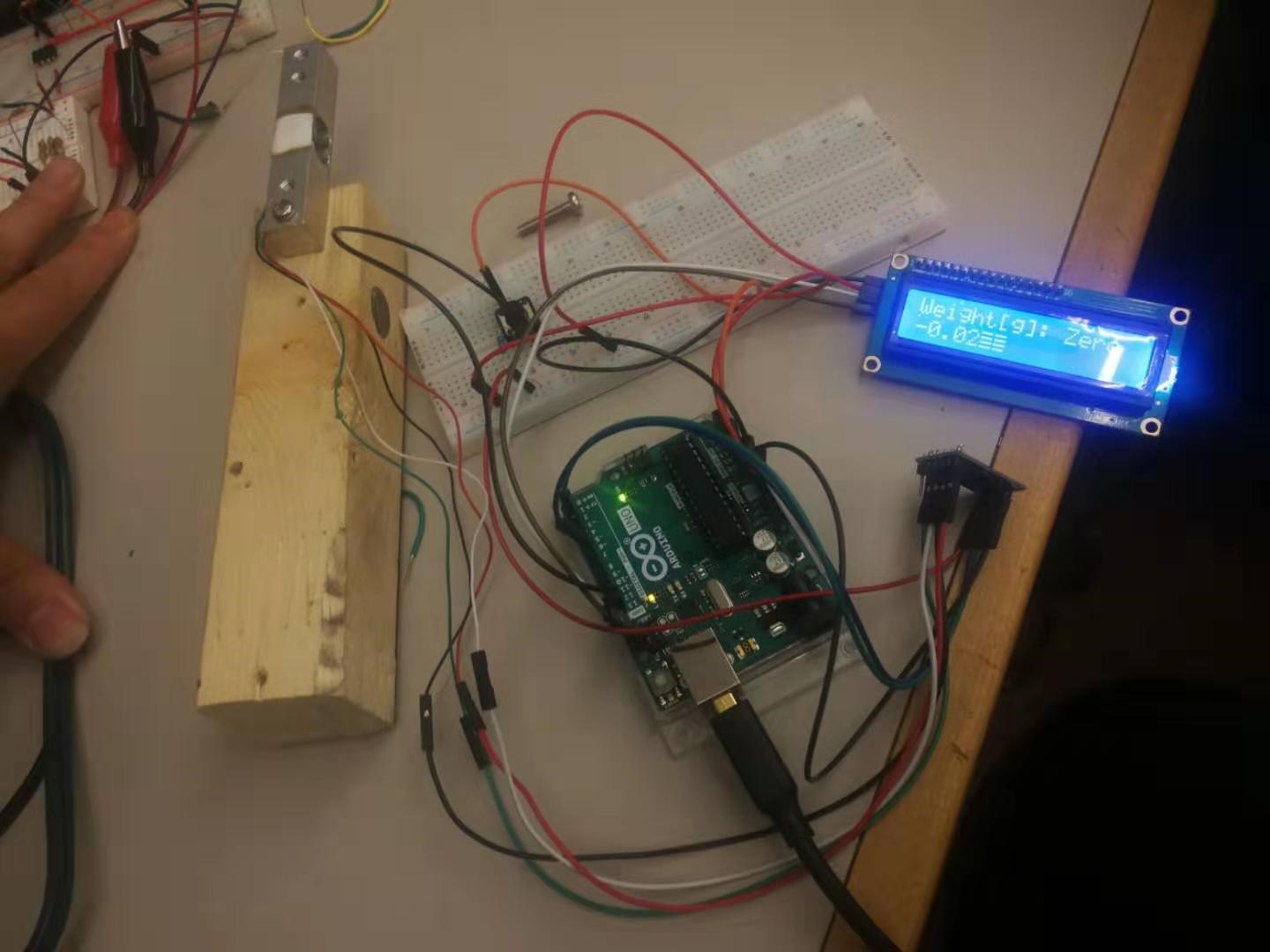
ELECTRONIC SCALE PROJECT
Created by: Tao You
Overview:
This electronic scale is operated by Arduino UNO, load cell, a load cell amplifier HX711 to amplify the signal from the load cell, and a 2X16 LCD display in order to show the weight in digital format.
Parts you will need:
- LCD DISPLAY 2X16 BLUE WITH I2C INTERFACE (Lee's ID: 23991)
- LOAD CELL – 10 KG STRAIGHT BAR (TAL220) (Lee's ID: 16227)
- ARDUINO UNO R3 (Lee's ID: 10997)
- FLAT RIBBON JUMPER CABLE 40 PIN F/M 210MM (Lee's ID: 21801)
- FLAT RIBBON JUMPER CABLE 40 PIN F/F 210MM (Lee's ID: 21800)
- LOAD CELL AMPLIFIER HX711 (Lee's ID:15673)
- BREADBOARD 400 HOLES (Lee's ID: 106981)
- TACTILE SWITCH 12X12X8 SPST (Lee's ID: 31242)
Step 1: Preparation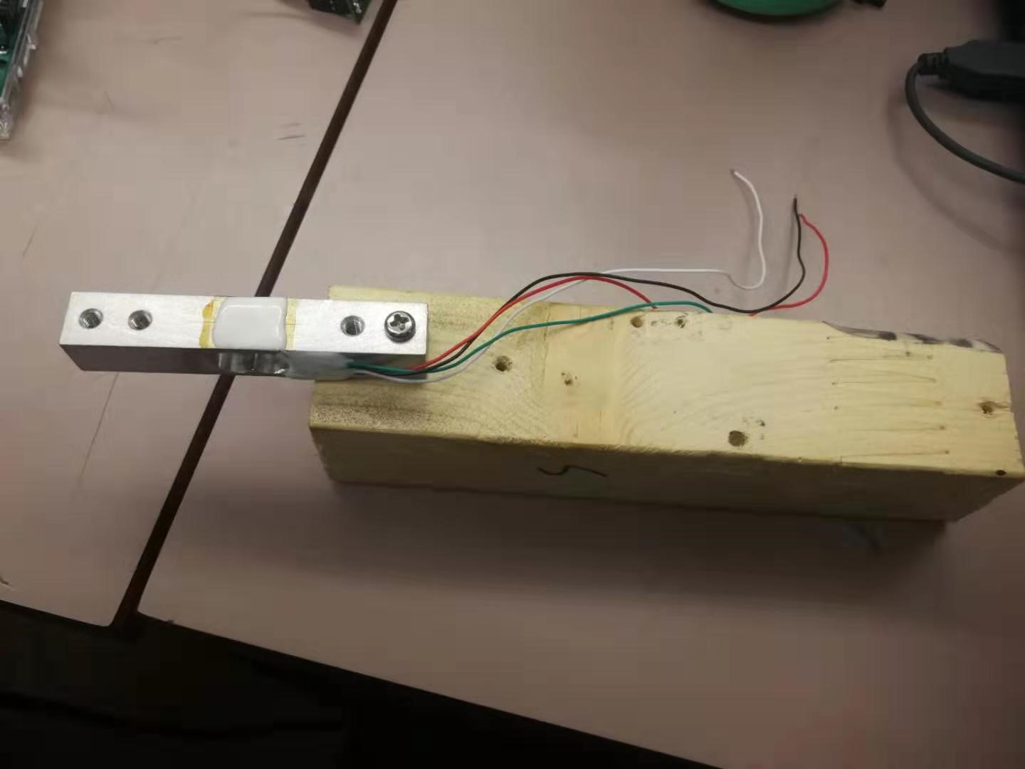
The working principle of the load cell is that the object’s weight will be measured by bending the aluminum load cell bar on either side of the bar. The white adhesive in the middle will calculate the load cell’s inner resistance when the bar is bending. Therefore, we can mount one side of the load cell to a stabilizing object, while connecting the wires on the opposite side. Here using a block of wood is a good stabilizing object since we can attach the load cell to the woodblock by using M4 screws.
Step 2: Soldering headers on the load cell amplifier
The HX711 load cell amplifier is a precision analog to digital converter designed for weighing objects. The product initially comes with the header separated. Therefore we need to solder/jump headers onto the 4-pin side, to generate communication with Arduino by utilizing male-female (M/F) jumper wires. As for the 6-pin side, we can solder the wires that come with the load cell directly: E+, E- represent the voltage positive (red wire on the load cell) and negative (black wire). A+, A- is the positive (white wire) and negative (green wire) for data.


Step 3: Building the switch circuit

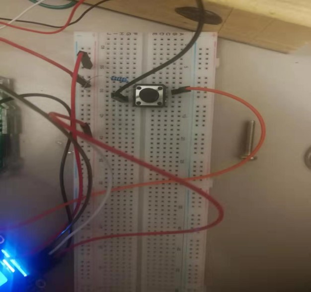
We can add a switch if we want the LCD keeping display zero due to the sensitivity of the load cell amplifier, otherwise, the LCD might display negative or non zero values. The switch is a 4-pin tactile switch, single pole single throw (SPST), momentary on and off switch which can handle 0.5A. Therefore, add a 10k ohm resistor to act as a pull-down resistor and by ignoring one pin the Arduino will receive HIGH state when the switch is off and LOW state when the switch is on because of the current flow.
Step 4: Coding and details
Here is the code I wrote:
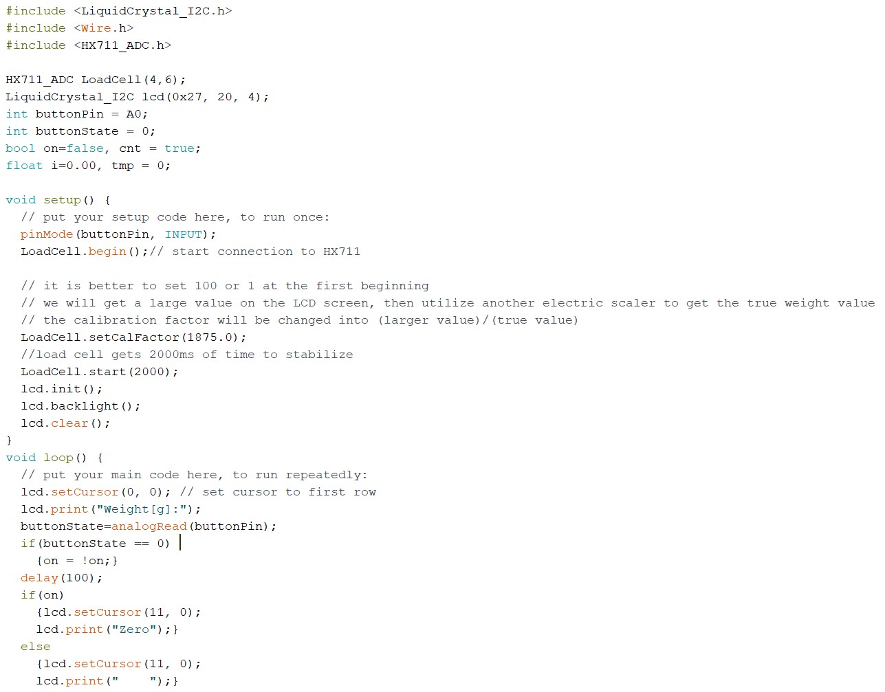

There are two essential libraries that need to be added into the Arduino IDE: The “HX711_ADC” by Olav Kallhovd and the LCD I2C library by John Rickman which can be downloaded from https://github.com/johnrickman/LiquidCrystal_I2C. The HX711_ADC library can be downloaded via Arduino IDE’s Library Manager and search HX711, then install the “HX711_ADC” one. To install John Rickman’s LCD I2C library, select “Sketch-Add file” in the Arduino IDE.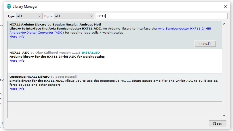
As for the LCD screen, we need to do solder or jump a lot of wires, so it is better to get LCD I2C which has a 4-pin connector only. The LCD I2C has pins called “SDA” and “SCL” which can connect into Arduino “SDL” and “SCL” pin respectively.
Finally, connect everything like the diagram below:
Step 5: A Video Demonstration
Related posts
-
 Touch Switch Circuit With Mosfet
10/19/20174448 viewsThe simple touch switch LED circuit utilizes biasing characteristics of the MOSFET.Read more
 -
 Egg Timer
11/16/20182904 viewsThis project demonstrates the basics of digital logic, the characteristics of a NE555 timer, and demonstrates how...Read more
 -
 Arduino Piano Project
10/23/20173052 viewsThis is a piano board with eight push button switches that allows you to play one octave (Do Re Mi Fa So La Si Do)...Read more
 -
 Small AC to DC Converter
03/16/20183298 viewsThe small AC to DC Voltage Converter project uses four diodes to make one bridge rectifier to transfer AC power to DC...Read more
 -
 RF Remote Control Car
03/09/20174121 viewsThe RC car is a great project for all ages and it doesn’t require any programming. It uses simple integrated circuits...Read more


.png)
