How we will approach our orders going forward with the CUPW strike.
Store address and hours
location_on 4131 Fraser St. Vancouver BC Get Directions
phone 604-875-1993 Call us
access_time Hours
| Monday - Friday | 9AM - 5:30PM |
| Saturday - Sunday & Holidays | Closed | See Holiday Hours |

-
 close
close -
CATEGORIES
-
-
-
-
-
-
-
-
-
-
-
-
-
Featured Items
-
-
-
-
-
-
-
More mirco-controllers
-
More Developement Tools
-
-
More Prototyping
-
More Modules
-
-
Featured Items
-
More prototyping Tools
-
-
-
-
-
-
-
-
Featured Item
-
-
-
-
-
-
-
Featured Items
-
-
-
-
-
-
-
-
-
-
Featured Items
-
-
-
-
-
-
-
-
-
-
-
Featured Items
-
-
-
-
-
-
-
-
-
Featured Items
-
-
-
-
-
-
Popular Cleaners
-
-
-
Featured Items
-
-
-
-
-
-
-
Featured Items
-
-
-
-
-
Featured Items
-
-
-
-
Featured Products
-
-
-
-
-
more motor
-
-
more power supplies
-
-
Featured Items
-
-
-
more electrical devices
-
-
-
-
-
-
-
Featured Items
-
-
-
-
-
-
BRANDS
-
- PROJECTS
-
COMMUNITY
-
-
-
FEATURED POSTS
-
-
-
- SALE
Keyless Unlock System
Created by Simon Lee
Overview:
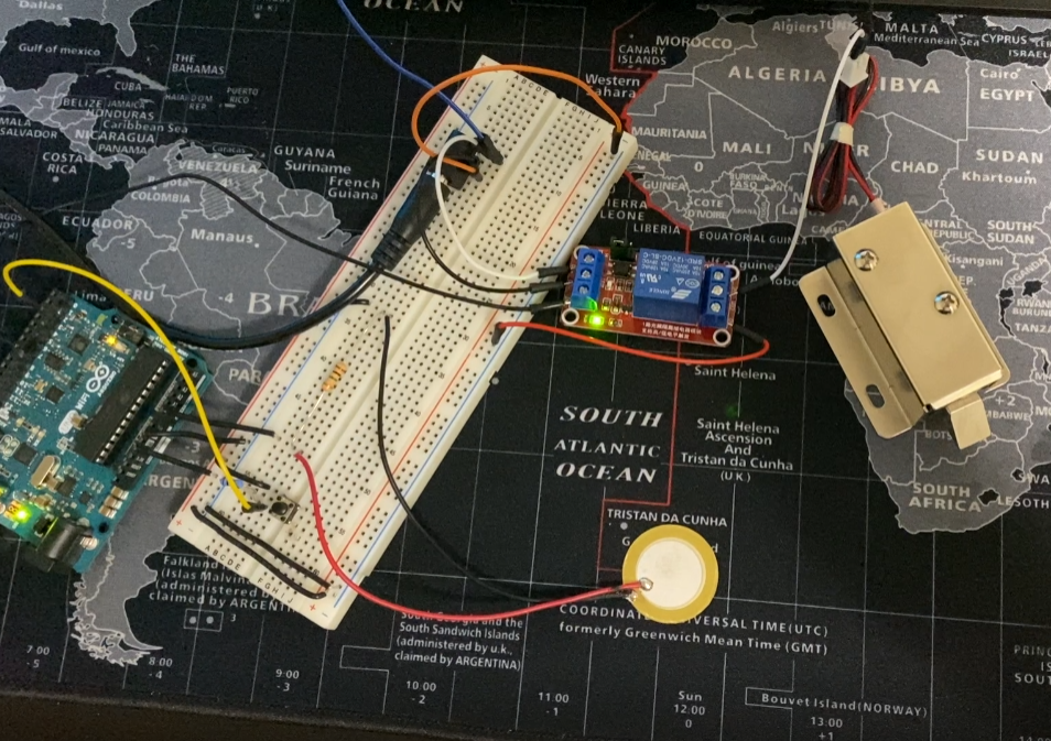
This project is designed to keylessly lock and unlock the door by knocking. The device makes it convenient for the user since the user does not need a key to lock the door especially when the user is racing against time. Users can unlock the door by using a secret knock, the secret knock pattern can easily be changed by a user.
Supplies
In order to achieve this project, the essential components are shown below:
- PIEZO ELEMENT W/WIRE (7BB-20-6L0) X 1 (PID:18584)
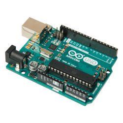
- ARDUINO UNO REV3 X 1 (PID: 10997)
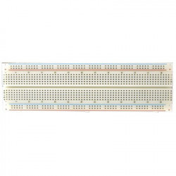
- CIRCUIT TEST BREADBOARD 830 TERMINALS MB-102 X 1 (PID: 10683)
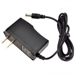
- TACK SWITCH SMD 4.3MM MTS1132 X1 (PID: 3388)
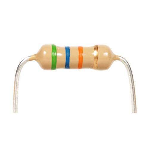
- RESISTORS 1/2W 1MEG 5% 10PCSX 1 (PID: 9608)
- RESISTORS 1/2W 100K 5% 10PCS X 1 (PID: 9586)
- HOOK UP WIRE 22AWG SOLID UL1007 BLACK - 50FT/SPOOL X 1 (PID: 224900)
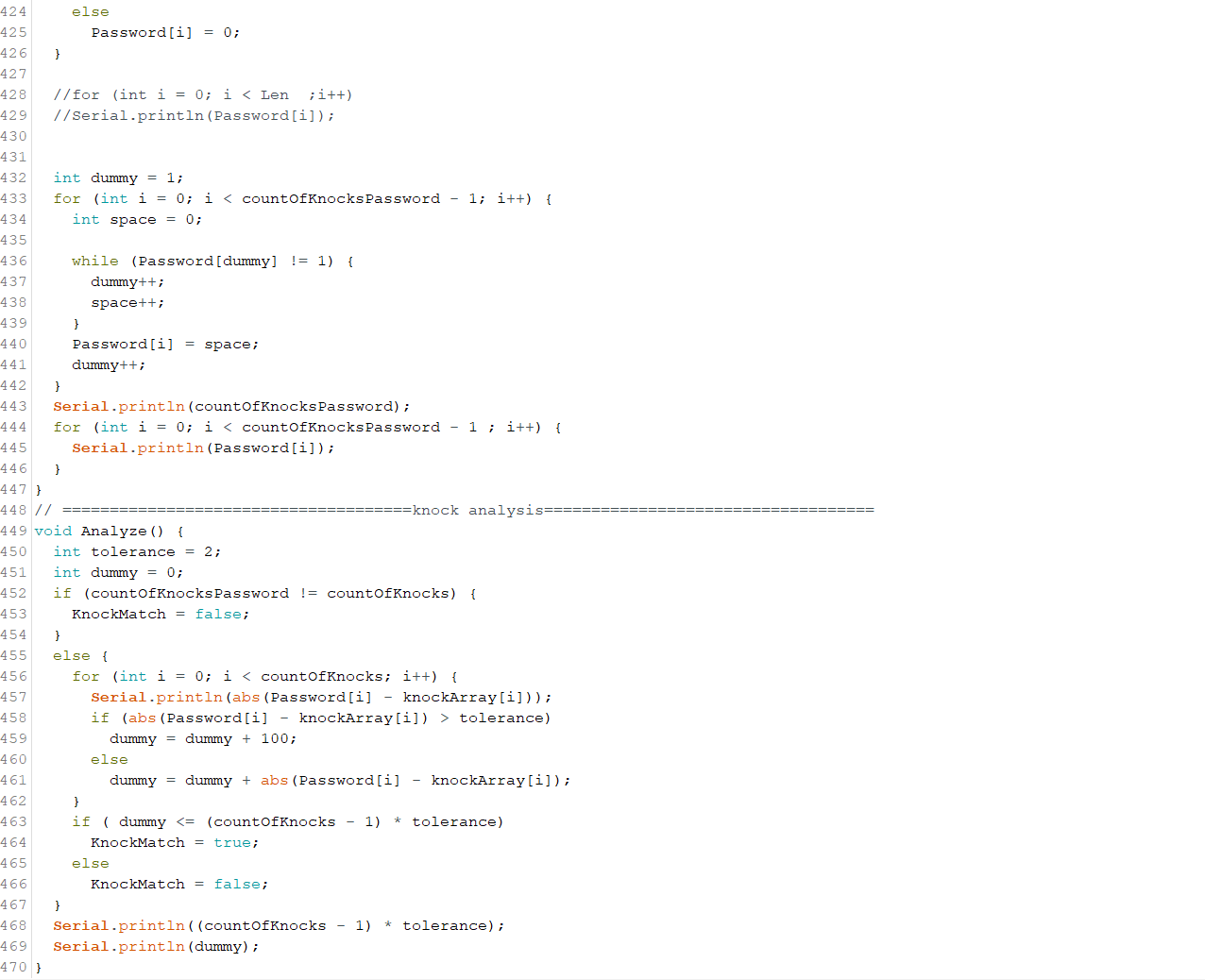
- POWER ADAPTER, AC/DC, SWITCHING, 12V, 1A, CEN + X 1 (PID: 1452)
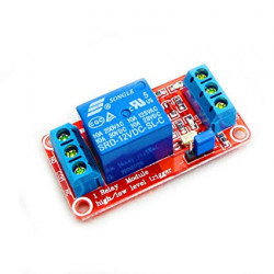
- RELAY MODULE 1-RELAY SPDT 12VDC HIGH/LOW TRIGGER X 1 (PID: 18405)
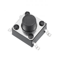
- 12V SOLENOID (LATCH/LOCK) X 1 (PID: 4404)
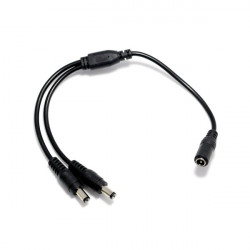
- 2.1MM POWER JACK TO 2 X 2.1MM PLUGS SPLITTER X1 (PID: 21113)
Step 1: Setup Piezo Sensor
Piezo sensor converts press or squeeze into measurable electrical charges. By observing the value of the electrical charges, the knocking pattern can be extracted. The circuit of the piezo sensor shows above, the piezo sensor connected parallelly with a 1M Ohm resistor and to the ground and analog pin on the Arduino UNO.
Step 2: Setup Push Button
The function of the push button is to change the knock password, when the push button is pressed and held, the system will erase the existing knock password, meanwhile, the system records the knocks pattern until the button has been released. The system records the new knock pattern and saves it as a new password. The circuit of the button shows above, the resistance used in this circuit is 100K OHM.
Step 3: Setup Solenoid
To lock and unlock the door, a 12V solenoid is used. The solenoid is a normally closed device, the latch unlocks when the solenoid is activated by a 12V power and vice versa. Arduino Uno can only output 5V and 3.3V which cannot activate the 12V solenoid. To solve this problem a 12V relay module shown is needed.
The figure above with a red board is the structure of the relay module (PID: 18405), DC+ and DC- connect to the 12VDC power. The pin IN controls the connection of the output pins (NO, COM, and NC), NO and COM connect together when pin IN receives 5V and vice versa. In this project, the pin IN is controlled by the Arduino UNO and the circuit shown above.
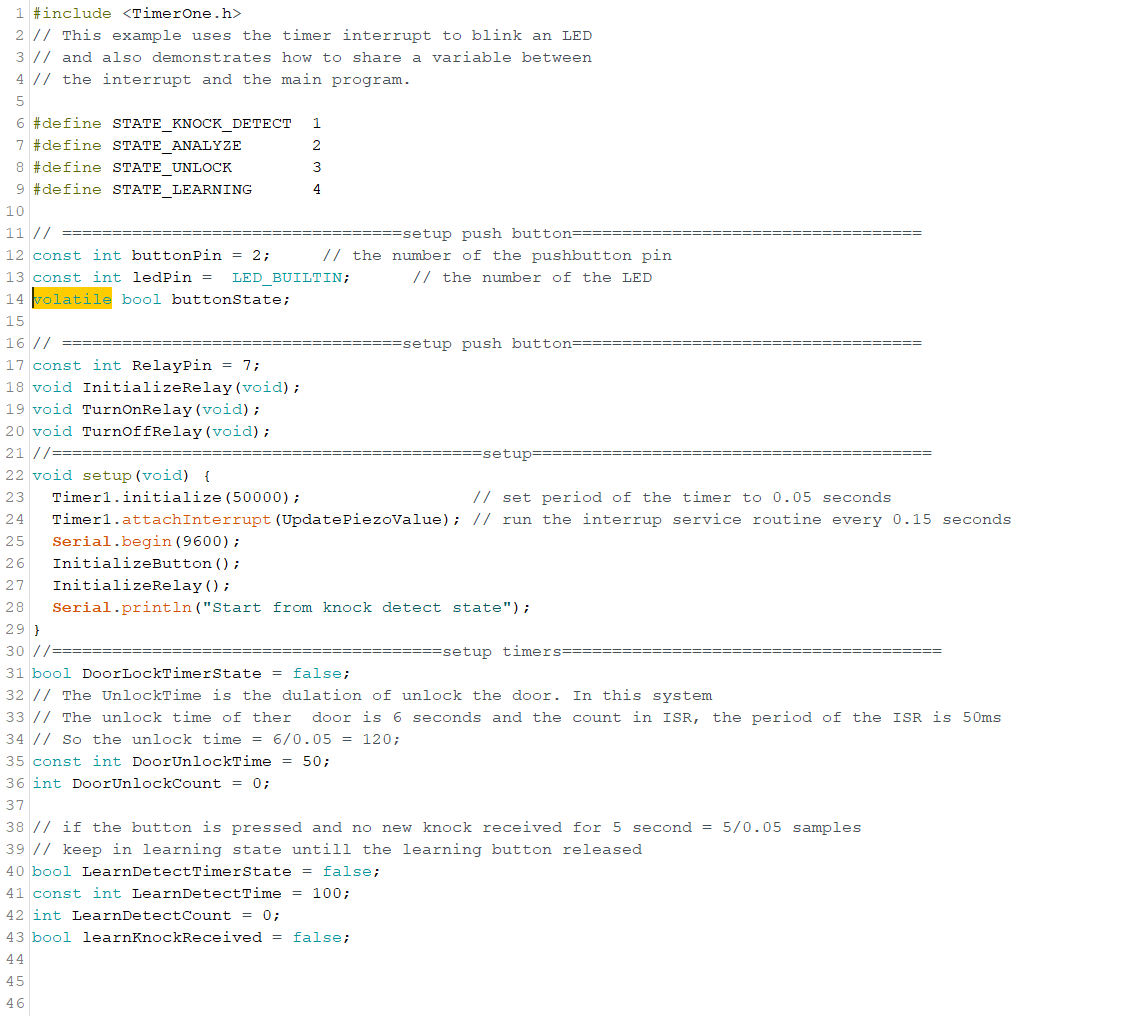
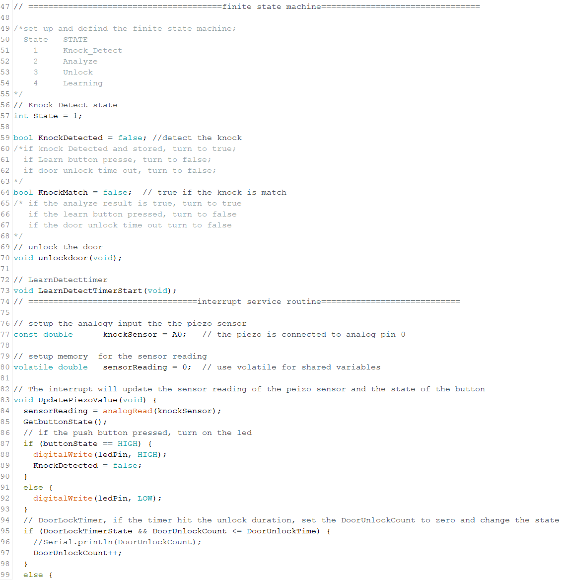
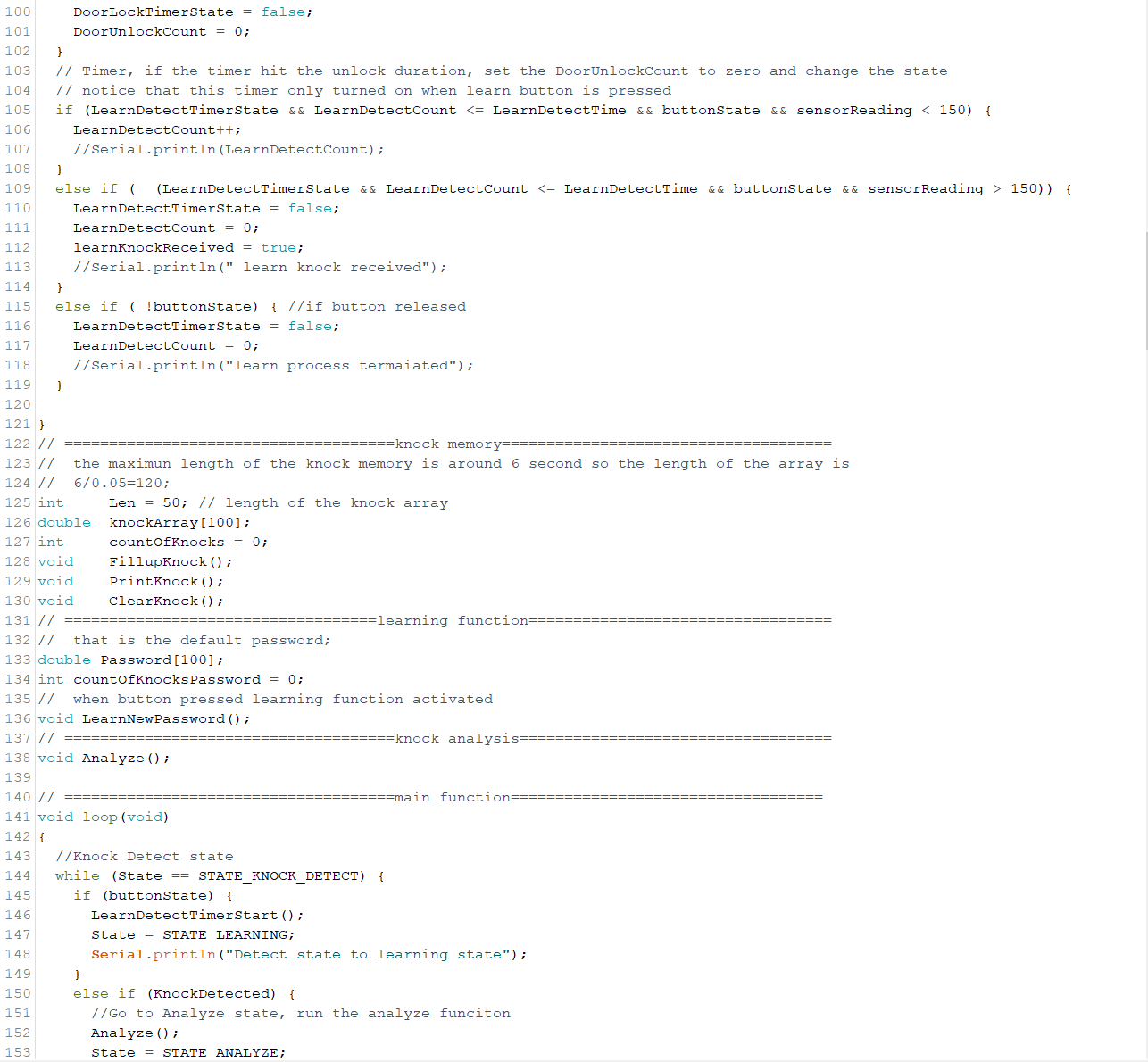
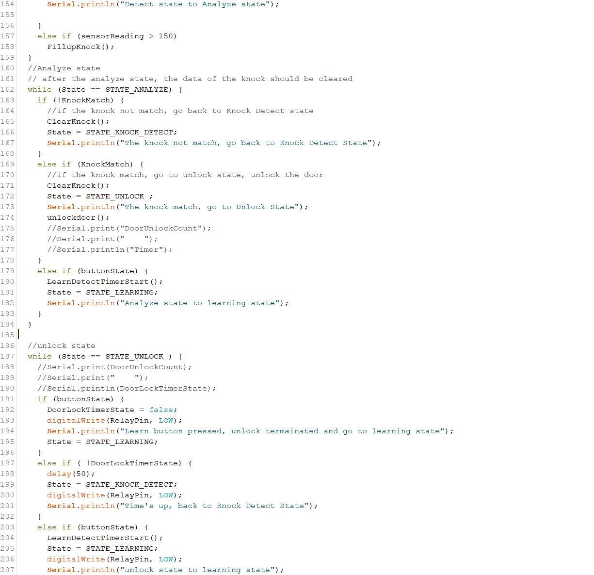
Step 4: Coding
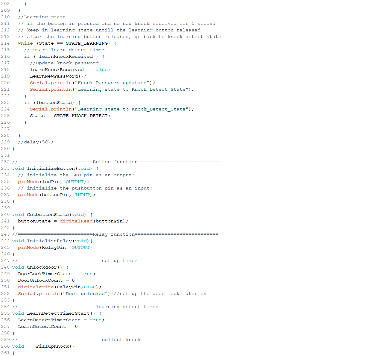
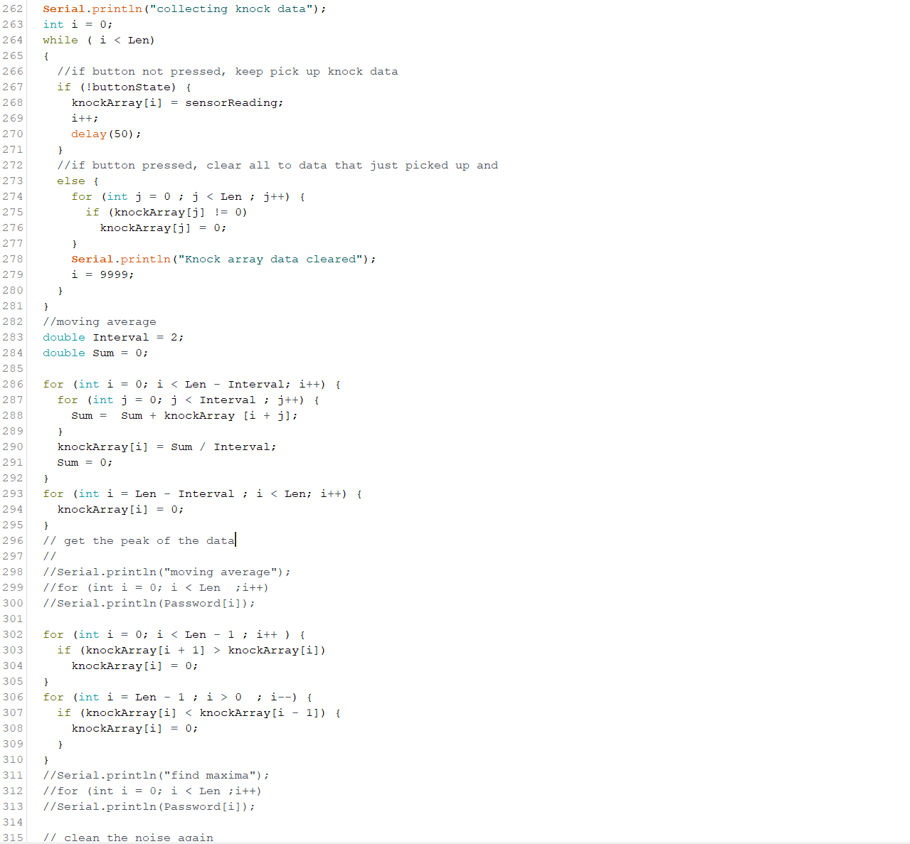
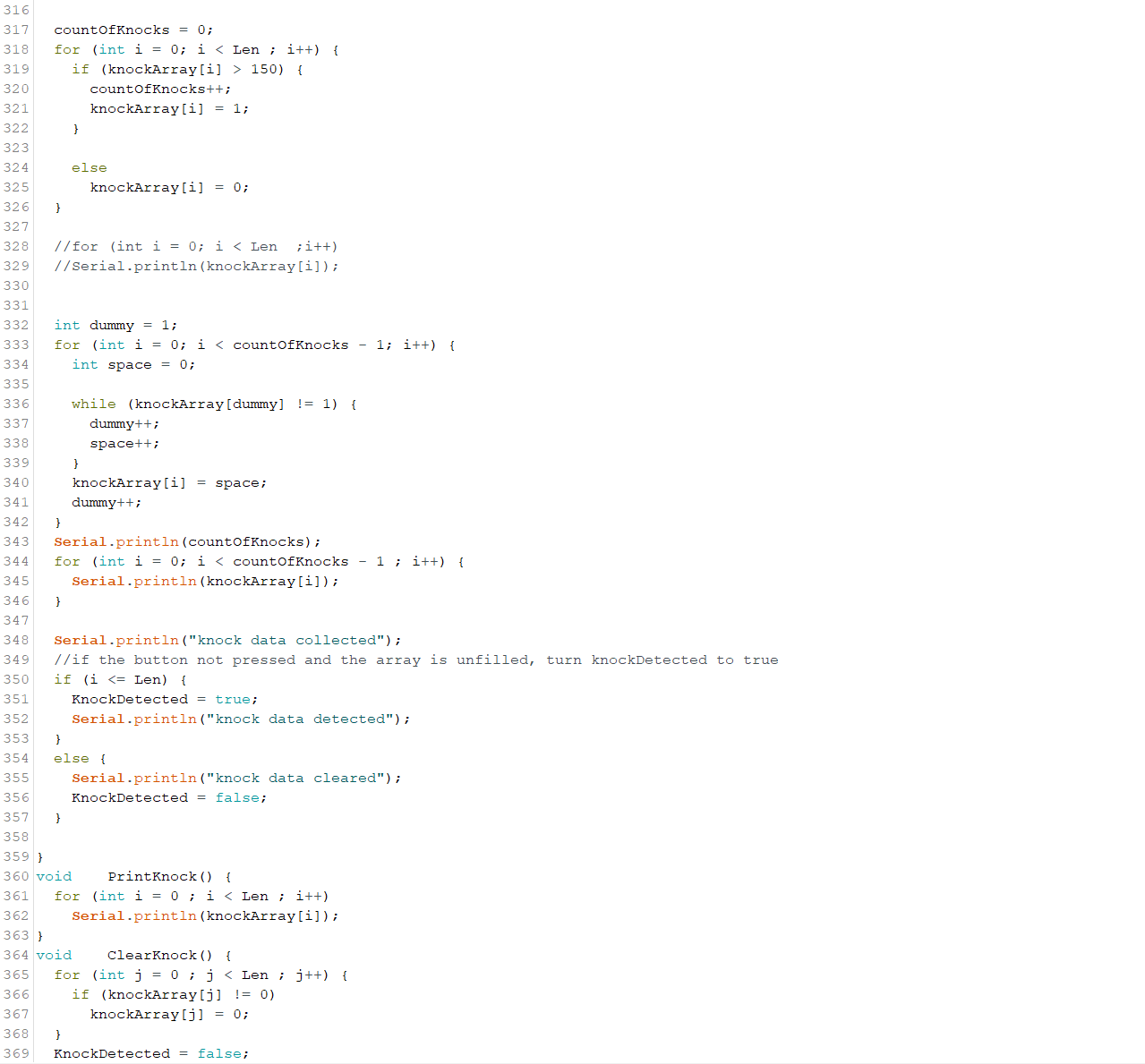
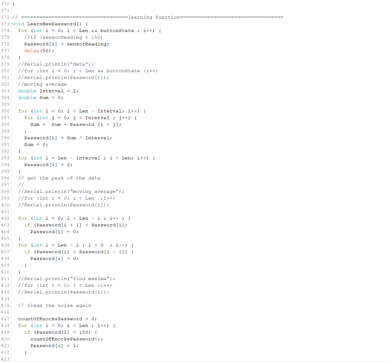
Step 5: Code Explanation
There are four states for the finite state machine which are Detecting State, Analysing State, Unlock State, and Reset State.
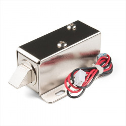
In the detect state, the machine keeps checking for the knock pattern from the user, this process loops forever until the machine receives a knock from the user or when the push button is pressed. If the push button is pressed, the machine jumps to the reset state. If the machine receives the knock pattern from the user, the machine jumps to analyzing state and starts analyzing the knock pattern. The analysis of the knock pattern will be discussed in the next section.
In analyzing state, if the knock pattern matches, it jumps to unlock state, starts the timer, and unlocks the solenoid. If the knock pattern does not match, the machine jumps back to the detect state. If the reset button is pressed, the analyzing process will be terminated and go to the reset state.
In unlock state, the machine keeps checking the timer. If the timer reaches the desired time(6 seconds in this project), the solenoid locks the latch again or vice versa. If the reset button is pressed, the machine will lock the solenoid, terminate the timer, and jump to the reset state.
In the reset state, if the reset button is held, the system records all the knocks patterns from the piezo sensor and the old password will be overridden by the new knocks patterns. If the reset button is held but the new password is not received, the password will not be updated. When the button is released, the machine jumps back to detect the state and waits for the knocking signal.
Step 6: Data Analysis
After the knock pattern is received, the system compares the knock by the user and the knock password. The data from the piezo sensor cannot be used to analyze since raw data has a lot of noise from the environment and different kinds of uncertainties.
We can easily visualize all the local maximums of the raw data, but the microcontroller cannot do it. Some manipulation applies to the data, first, we use the moving average to smooth the noise, then find the local maximums. After filtering the data, the data only shows the knocks as a pulse. By comparing the width of the pulse, we can identify the knock by the user and the password.
Step 7: Video Demonstration
Related products
-
POWER ADAPTER, AC/DC, SWITCHING, 12V, 1A, CEN+
Price: CA$8.50POWER ADAPTER, AC/DC, SWITCHING, 12V, 1A, CEN + 2.1.MM BARREL PLUG. -
-
12V SOLENOID (LATCH/LOCK)
Price: CA$15.0012V Solenoid (Latch / Lock) Features an electronic lock Can be paired with a... -
RESISTORS 1/2W 100K 5% 10PCS
Price: CA$0.85 -
RESISTORS 1/2W 1MEG 5% 10PCS
Price: CA$0.85 -
CIRCUIT TEST BREADBOARD 830 TERMINALS MB-102
Price: CA$9.00Circuit-Test Solderless Breadboards allow you to easily assemble and test... -
ARDUINO UNO Rev3
Price: CA$33.00The Arduino Uno Rev3 is a microcontroller board based on the ATmega328... -
RELAY MODULE 1-RELAY SPDT 12VDC HIGH/LOW TRIGGER
Price: CA$6.00 -
PIEZO 20MM ELEMENT W/WIRE (7BB-20-6L0)
Price: CA$3.50 -
2.1MM POWER JACK TO 2 X 2.1MM PLUGS SPLITTER
Price: CA$4.002.1MM POWER JACK TO 2 X 2.1MM PLUGS SPLITTER -
HOOK UP WIRE 22AWG SOLID UL1007 BLACK - 50FT/SPOOL
Price: CA$7.50
Related posts
-
 Touch Switch Circuit With Mosfet
10/19/20174448 viewsThe simple touch switch LED circuit utilizes biasing characteristics of the MOSFET.Read more
 -
 Egg Timer
11/16/20182903 viewsThis project demonstrates the basics of digital logic, the characteristics of a NE555 timer, and demonstrates how...Read more
 -
 Arduino Piano Project
10/23/20173047 viewsThis is a piano board with eight push button switches that allows you to play one octave (Do Re Mi Fa So La Si Do)...Read more
 -
 Small AC to DC Converter
03/16/20183297 viewsThe small AC to DC Voltage Converter project uses four diodes to make one bridge rectifier to transfer AC power to DC...Read more
 -
 RF Remote Control Car
03/09/20174118 viewsThe RC car is a great project for all ages and it doesn’t require any programming. It uses simple integrated circuits...Read more


.png)
