How we will approach our orders going forward with the CUPW strike.
Store address and hours
location_on 4131 Fraser St. Vancouver BC Get Directions
phone 604-875-1993 Call us
access_time Hours
| Monday - Friday | 9AM - 5:30PM |
| Saturday - Sunday & Holidays | Closed | See Holiday Hours |

-
 close
close -
CATEGORIES
-
-
-
-
-
-
-
-
-
-
-
-
-
Featured Items
-
-
-
-
-
-
-
More mirco-controllers
-
More Developement Tools
-
-
More Prototyping
-
More Modules
-
-
Featured Items
-
More prototyping Tools
-
-
-
-
-
-
-
-
Featured Item
-
-
-
-
-
-
-
Featured Items
-
-
-
-
-
-
-
-
-
-
Featured Items
-
-
-
-
-
-
-
-
-
-
-
Featured Items
-
-
-
-
-
-
-
-
-
Featured Items
-
-
-
-
-
-
Popular Cleaners
-
-
-
Featured Items
-
-
-
-
-
-
-
Featured Items
-
-
-
-
-
Featured Items
-
-
-
-
Featured Products
-
-
-
-
-
more motor
-
-
more power supplies
-
-
Featured Items
-
-
-
more electrical devices
-
-
-
-
-
-
-
Featured Items
-
-
-
-
-
-
BRANDS
-
- PROJECTS
-
COMMUNITY
-
-
-
FEATURED POSTS
-
-
-
- SALE
Small AC to DC Converter
Created By: Haotian Ye
Overview:
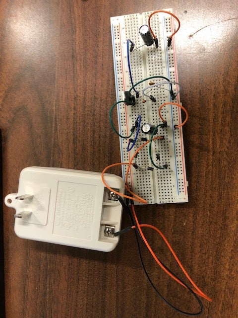
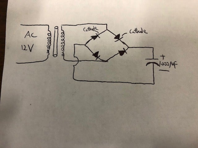
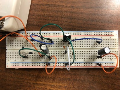
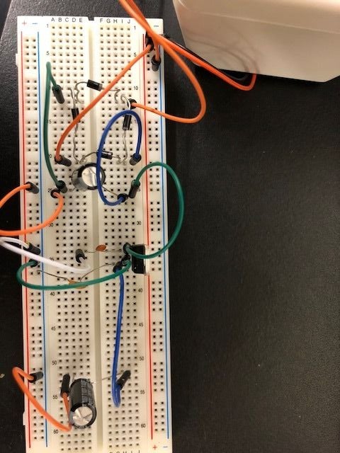
The small AC to DC Voltage Converter project uses four diodes to make one bridge rectifier to transfer AC power to DC power. Also, we use capacitors to remove ripples in the circuit. After we transfer from AC power to DC power, we need to use one 5v voltage regulator to give 5v DC output from 12 v DC output.
Parts You Will Need:
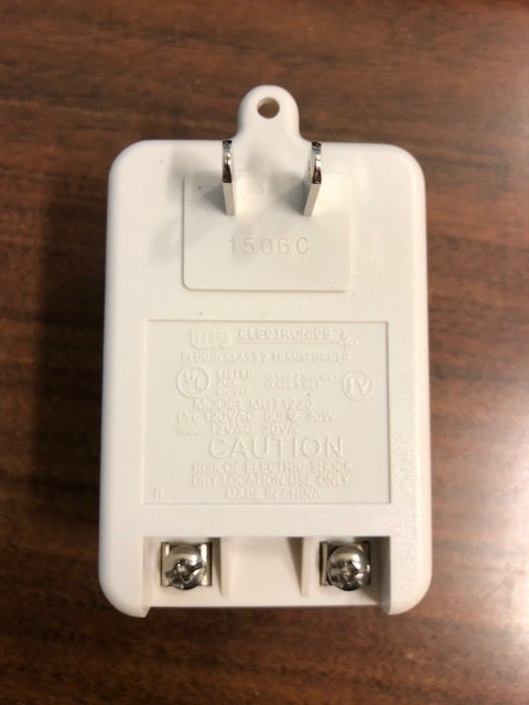
Transformer 12VAC 20VA (Lee's ID:10641)
IN4001 Diode (Lee's ID:796)
16V 1000UF Electrolytic Cap (Lee's ID:867)
50V 0.1UF Ceramic Cap (Lee's ID:8175)
50V 0.22UF Ceramic Cap (Lee's ID:8174)
Breadboard (Lee's ID:10686)
Jumper Wires (Lee's ID: 21802)
Mini Voltage Display (Lee's ID:1265)
IC Regulator 7805 +5V 1A (Lee's ID:7115)
Step 1: Choose the Transformer
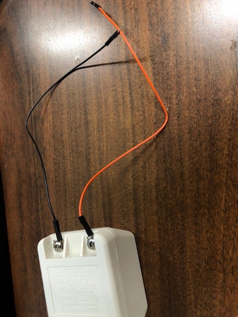
In this project we choose a 12VAC 20VA transformer with screws at the bottom. In order to power the circuit with this transformer, we have to screw the jumer wire pin inside and plug to the breadboard. Because this is an AC power supply, the positive and negative side does not matter.
Step 2: Build the Bridge Rectifier With One Capacitor in Parallel With It
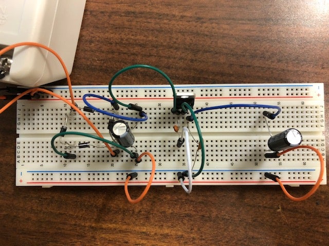
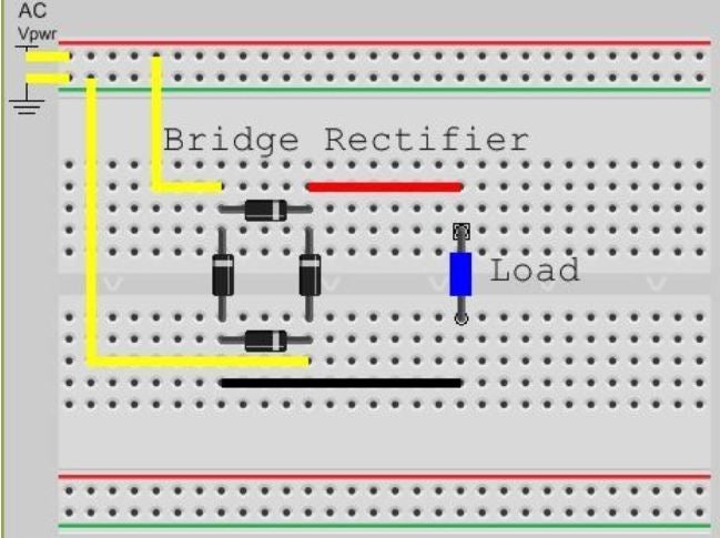
In this step, we build an bridge rectifier which make up of four 1N4001 diodes. Then, we parallel this rectifier with an 1000uf parallel to remove some ripple. The thing need to be noticed is the polarity, remember the silver line on the diode indicates that it is a cathode terminal. After finishing building, please use mini voltage display to test the voltage across the capacitor. It will give you an around 18v DC power.
Step 3: Add the Voltage Regulator to Give 5v DC Output
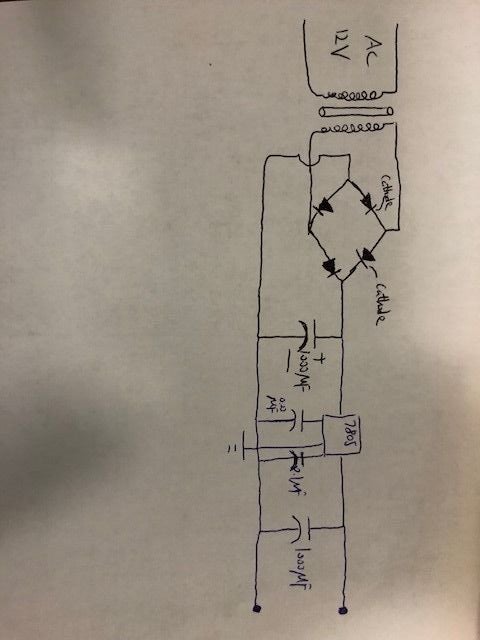
In this step, we need to use the 5v IC Regulator, one 0.1uf ceramic capacitor, one 0.22uf ceramic capacitor and one 1000uf electrolytic capacitor. For the IC regulator, with the lead on the bottom, the left is input, the middle is ground and the right is output. After finishing building the circuit, you can use voltage display to test the output voltage by paralleling it with the last 1000uf capacitor. You will see the output is 5v DC.
Step 4: Future Improvement
In this project, we can only have a 5v DC output. However, we can try to figure out output any voltage from 0v to 12v DC. This can be solved by replacing Voltage regulator 7805 with a variable voltage regulator LM317.
Related posts
-
 Touch Switch Circuit With Mosfet
10/19/20174448 viewsThe simple touch switch LED circuit utilizes biasing characteristics of the MOSFET.Read more
 -
 Egg Timer
11/16/20182904 viewsThis project demonstrates the basics of digital logic, the characteristics of a NE555 timer, and demonstrates how...Read more
 -
 Arduino Piano Project
10/23/20173052 viewsThis is a piano board with eight push button switches that allows you to play one octave (Do Re Mi Fa So La Si Do)...Read more
 -
 RF Remote Control Car
03/09/20174121 viewsThe RC car is a great project for all ages and it doesn’t require any programming. It uses simple integrated circuits...Read more
 -
 Magnetic Railgun
09/19/20175435 viewsThe concept of a railgun consists of propelling a conducting object along 2 conducting rails due to a magnetic force...Read more


.png)
