How we will approach our orders going forward with the CUPW strike.
Store address and hours
location_on 4131 Fraser St. Vancouver BC Get Directions
phone 604-875-1993 Call us
access_time Hours
| Monday - Friday | 9AM - 5:30PM |
| Saturday - Sunday & Holidays | Closed | See Holiday Hours |

-
 close
close -
CATEGORIES
-
-
-
-
-
-
-
-
-
-
-
-
-
Featured Items
-
-
-
-
-
-
-
More mirco-controllers
-
More Developement Tools
-
-
More Prototyping
-
More Modules
-
-
Featured Items
-
More prototyping Tools
-
-
-
-
-
-
-
-
Featured Item
-
-
-
-
-
-
-
Featured Items
-
-
-
-
-
-
-
-
-
-
Featured Items
-
-
-
-
-
-
-
-
-
-
-
Featured Items
-
-
-
-
-
-
-
-
-
Featured Items
-
-
-
-
-
-
Popular Cleaners
-
-
-
Featured Items
-
-
-
-
-
-
-
Featured Items
-
-
-
-
-
Featured Items
-
-
-
-
Featured Products
-
-
-
-
-
more motor
-
-
more power supplies
-
-
Featured Items
-
-
-
more electrical devices
-
-
-
-
-
-
-
Featured Items
-
-
-
-
-
-
BRANDS
-
- PROJECTS
-
COMMUNITY
-
-
-
FEATURED POSTS
-
-
-
- SALE
Auto Brightness Adjusting LED Strip

This project is an automatically dimmable LED strip light. This project is aimed towards beginners in electronics, or those who have some electronics knowledge or experience. This project will provide an opportunity to learn about PWM (pulse width modulation) and the 555 timer IC in order to regulate the dimming of an LED strip light.
The purpose of this project is to provide adequate lighting no matter the ambience of the room. The brightness of the LED strip would be determined based on the lighting situation of the room it is in. For example, if the time of day is morning and the room is already well lit, the LED strip light would remain off or at very low brightness. However, if it is late at night and there is little to no light in the room, the LED strip would be near 100% brightness.
Supplies
All supplies can be purchased here at https://leeselectronic.com
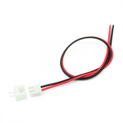
- JST XH 2 pin jumper wire #28602
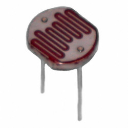
- LDR photoresistor 1K-3M #71862
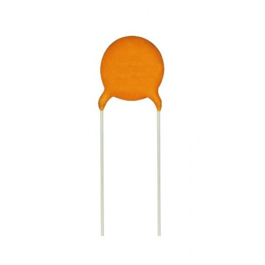
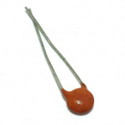
- Ceramic capacitor 50V 0.1uF #8175
Step 1: Wiring the Breadboard


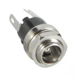
Before soldering onto a PCB, it is always a good idea to build the circuit on a breadboard and test. Build the above circuit using the schematic shown above. Connect the LED strip or a 12V LED from the 1K resistor to GND. To test, plug in a 12V 1A (center positive) AC/DC power adapter into the 2.1mm DC power jack, and try waving your hand over the LDR to make the area darker. If the LED brightness changes, then the circuit is working.
Step 2: Soldering the Circuit


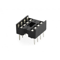
Once the breadboard circuit is working, it is time to solder it onto a PCB. Solder the 8-pin IC socket onto the board rather than soldering the 555 timer directly, in case the IC needs to be replaced at any point. Solder all the necessary connections. You may need to use a short length of solid wire to join components that are further away. Use the above picture as an example of how to solder the connections together. Leave 2 wires (VCC and GND) disconnected on one end, these will connect to the LED strip.
Step 3: Connecting the LED Strip
Using the JST 2 pin jumper wires, solder the leads onto the leads of the LED Strip. Then crimp or solder the JST pins onto the 2 wires left disconnected on the soldered PCB circuit. Push these pins into the male end of the JST jumper wire. Plug in the 2 ends of the JST connectors together to connect the LED Strip.
Step 4: Powering the Circuit
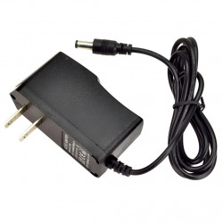
Power the circuit using a AC/DC 12V 1A power adapter. Make sure the adapter is center positive. LED strips typically use about 1A per meter, so if you wish to use a longer LED strip, simply use a 12V power adapter with a higher current rating.
Step 5: Video Demonstration
Disclaimer: Flicker is caused by camera capturing faster than PWM signal
Step 6: Wrapping Up
The LED strip dims using PWM and the 555 timer.
By pulsing the voltage being sent to the LED strip, it gives the effect that the LED strip is dimming, although in reality it is flashing at a rate which the human eye is unable to see. This circuit can be used in multiple situations. Some examples include lighting for a staircase or lighting for clothing at night.
Related products
-
POWER ADAPTER, AC/DC, SWITCHING, 12V, 1A, CEN+
Price: CA$8.50POWER ADAPTER, AC/DC, SWITCHING, 12V, 1A, CEN + 2.1.MM BARREL PLUG. -
-
-
DIODE RECTIFIER 1N4007 1000V 1A 4PCS
Price: CA$0.60 -
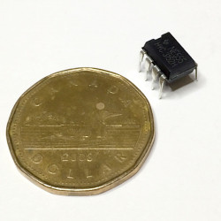
IC NE555P TIMER CIRCUIT
Price: CA$0.90The super popular 555 timing circuit. Used in a variety of timer, pulse... -
CERAMIC CAP 50V 0.1UF (104) 10PCS
Price: CA$0.80 -
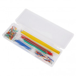
BREADBOARD JUMPER WIRE SET MB-900 (0165-011-000)
Price: CA$8.50 -
SOLDERING IRON,GAOJIE,40W,NO640
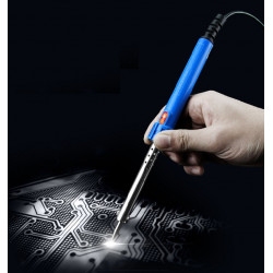
Price: CA$12.95GaoJie 640 40W 120V soldering iron for small hobby soldering work. -
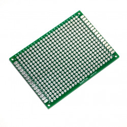
PROTOTYPING PCB, 50x70MM, DOUBLE SIDED, PLATED
Price: CA$3.80PROTOTYPING PCB, 50x70MM, DOUBLE SIDED, PLATED -
BREADBOARD EIC-102 (165-40-1020)
Price: CA$9.70Full size standard breadboard. If you are looking for a plain and simple... -
-
-
JUMPER WIRE, JST, XH, 2PIN, 2.50MM (M/F) SET
Price: CA$1.75JUMPER WIRE, JST, XH SERIES, 2PINS, 2.50MM (M/F) SET -
-
RESISTORS 1/4W 56KOHM 5% 10PCS
Price: CA$0.70 -
-
Related posts
-
 BCTEA Conference 2018
Posted in: Community09/16/20182226 views"The British Columbia Technology Education Association (BCTEA) is a Provincial Specialist Association (PSA) of the...Read more
 -
 Maker Faire Vancouver 2019
Posted in: Community09/05/20191793 viewsVancouver Maker Faire 2019 is being hosted at Science World! We hope to see you there!Read more
 -
 Vancouver Hack Space New Location
Posted in: Community09/06/20192292 viewsOur friends at Vancouver Hack Space (VHS) are moving to 1601 Veneables Street! Meet them up at their grand opening on...Read more
 -
 Metro Vancouver Repair Cafe
Posted in: Community09/06/20194078 viewsAre you a tinker looking to help out the community on your spare time? MetroVan Repair Cafe are looking for...Read more
 -
 Touch Switch Circuit With Mosfet
10/19/20174446 viewsThe simple touch switch LED circuit utilizes biasing characteristics of the MOSFET.Read more


.png)
