How we will approach our orders going forward with the CUPW strike.
Store address and hours
location_on 4131 Fraser St. Vancouver BC Get Directions
phone 604-875-1993 Call us
access_time Hours
| Monday - Friday | 9AM - 5:30PM |
| Saturday - Sunday & Holidays | Closed | See Holiday Hours |

-
 close
close -
CATEGORIES
-
-
-
-
-
-
-
-
-
-
-
-
-
Featured Items
-
-
-
-
-
-
-
More mirco-controllers
-
More Developement Tools
-
-
More Prototyping
-
More Modules
-
-
Featured Items
-
More prototyping Tools
-
-
-
-
-
-
-
-
Featured Item
-
-
-
-
-
-
-
Featured Items
-
-
-
-
-
-
-
-
-
-
Featured Items
-
-
-
-
-
-
-
-
-
-
-
Featured Items
-
-
-
-
-
-
-
-
-
Featured Items
-
-
-
-
-
-
Popular Cleaners
-
-
-
Featured Items
-
-
-
-
-
-
-
Featured Items
-
-
-
-
-
Featured Items
-
-
-
-
Featured Products
-
-
-
-
-
more motor
-
-
more power supplies
-
-
Featured Items
-
-
-
more electrical devices
-
-
-
-
-
-
-
Featured Items
-
-
-
-
-
-
BRANDS
-
- PROJECTS
-
COMMUNITY
-
-
-
FEATURED POSTS
-
-
-
- SALE
Touch Switch Circuit With Mosfet
Created by: Jonsen Li
Overview:
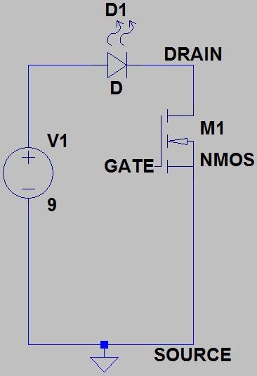
The simple touch switch LED circuit utilizes biasing characteristics of the MOSFET.
MOSFET stands for Metal-oxide-semiconductor field effect transistors. It is a voltage controlled device meaning that the current passing through the device is controlled by the voltage between two terminals.
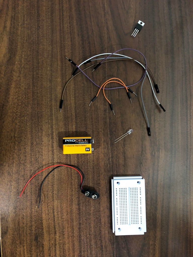
Parts you will need:
A power MOSFET (IRFZ-44 NPN) (Lee's ID: 71211)
9V battery (Lee's ID: 8374)
12V LED bulb (Lee's ID: 5504)
Jumper wires (Lee's ID: 21802)
Breadboard (Lee's ID: 10686)
9V battery clip (Lee's ID: 653)
Step 1: A Quick Tip to Keep in Mind
Since the mosfet is a voltage controlled device, it is very sensitive to electrostatic discharges and may be damaged due to the static charges flowing through the terminals.
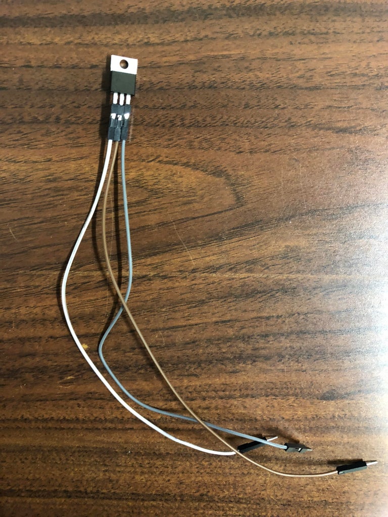
Step 2: Hooking Up Wires to the MOSFET
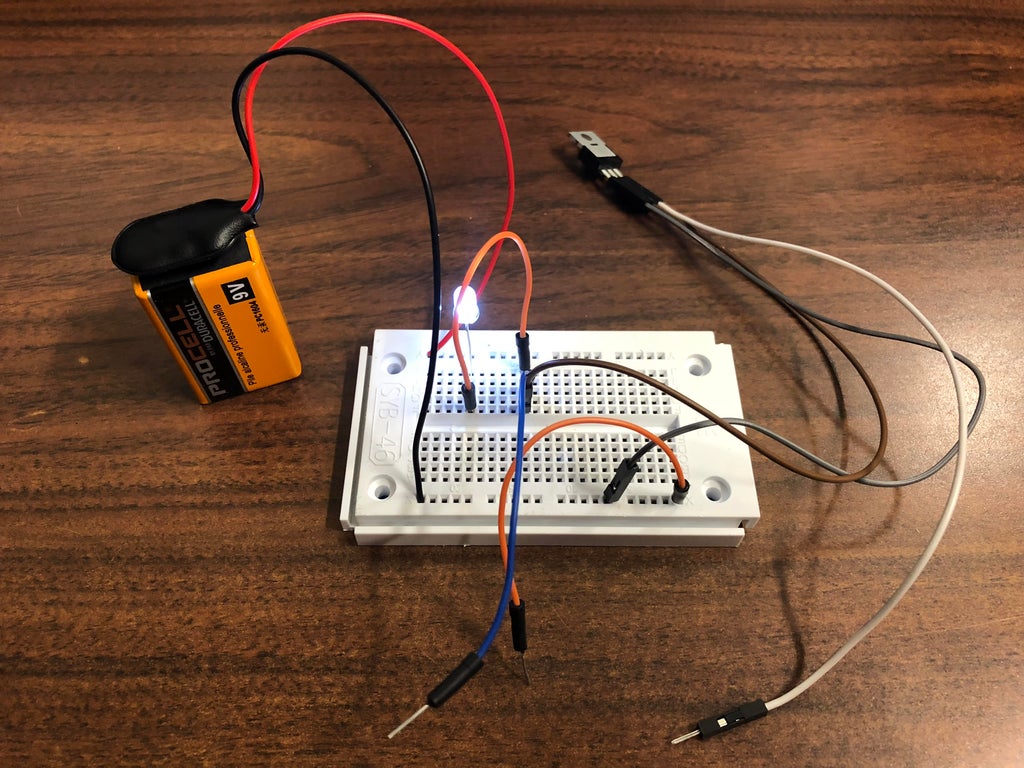
Simply connect the jumper terminals to the legs of the MOSFET
For IRFZ-44:
The left leg is the gate terminal (white jumper)
The middle is the drain terminal (brown jumper)
The right leg is the source terminal (grey jumper)
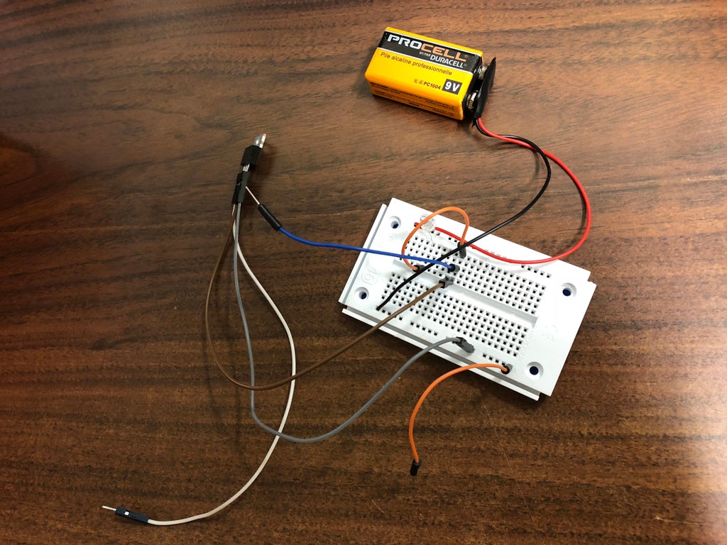
Step 3: Fully Assembled Circuit
To turn the LED on, simply touch the drain terminal and gate terminal at the SAME time.
To turn the LED off, touch the source terminal and gate terminal at the SAME time
The logic behind this project is the characteristics of the MOSFET:
For the LED to light up, the MOSFET must fully ON, which means Vds andgt; Vgs – Vt. Since MOSFETs are voltage-controlled transistors, touching the drain and gate terminal at the same time will “short” them, therefore allowing the MOSFET to be fully ON.
On the other hand, touching the gate and source terminal will turn the MOSFET fully OFF, because it cannot satisfy the overdrive voltage (Vov) requirement (Vov = Vgs – Vt, Vgs = 0V).
If you have difficulties turning the circuit on and off, wetting your hands may help.
Step 4: A Video Demonstration
Here is a quick video demonstration of the touch switch in action.
Related posts
-
 Egg Timer
11/16/20182911 viewsThis project demonstrates the basics of digital logic, the characteristics of a NE555 timer, and demonstrates how...Read more
 -
 Arduino Piano Project
10/23/20173062 viewsThis is a piano board with eight push button switches that allows you to play one octave (Do Re Mi Fa So La Si Do)...Read more
 -
 Small AC to DC Converter
03/16/20183301 viewsThe small AC to DC Voltage Converter project uses four diodes to make one bridge rectifier to transfer AC power to DC...Read more
 -
 RF Remote Control Car
03/09/20174123 viewsThe RC car is a great project for all ages and it doesn’t require any programming. It uses simple integrated circuits...Read more
 -
 Magnetic Railgun
09/19/20175438 viewsThe concept of a railgun consists of propelling a conducting object along 2 conducting rails due to a magnetic force...Read more


.png)
