.png)


How we will approach our orders going forward with the CUPW strike.
Blog categories
Search in blog
Latest posts
-
 About orders to be shipped out beginning November 15thRead more
 -
 Auto Brightness Adjusting LED StripRead more
In this tutorial we will show you how to build an Auto Brightness Adjusting LED Strip
-
 Switching to Paper Bags in 2022Read more
Starting January 4th 2022, Lee's Electronic will start to phase out white plastic bags for packaging goods in store.
-
 Lee's Electronic x Bare Conductive Back to School GiveawayRead more
Lee's Electronic and Bare Conductive are collaborating once again to host a giveaway! This time one winner will win...
-
 Lee's Electronic X Bare Conductive Giveaway 2Read more
Lee's Electronic and Bare Conductive is collaborating to host another giveaway! This time we're giving away an...
Featured posts
-
About orders to be shipped out beginning November 15thHow we will approach our orders going forward with the CUPW strike.Read more
-
Auto Brightness Adjusting LED StripIn this tutorial we will show you how to build an Auto Brightness Adjusting LED StripRead more
-
Switching to Paper Bags in 2022Starting January 4th 2022, Lee's Electronic will start to phase out white plastic bags for packaging goods in store.Read more
-
 Electric Gear Motor Back ScratcherA step-by-step tutorial on how to build an electric gear motor back scratcher. This project introduces the concepts...Read more
 -
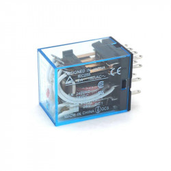
 Keyless Unlock SystemThis project is designed to keylessly lock and unlock the door by knocking. The device makes it convenient for the...Read more


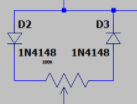
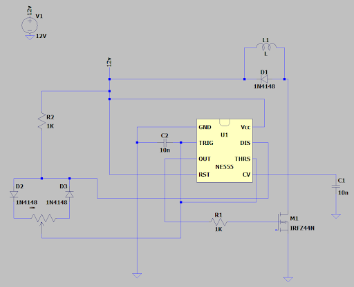

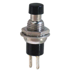
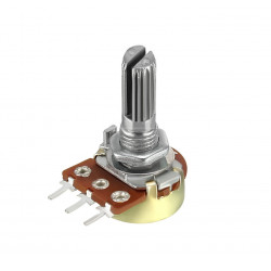
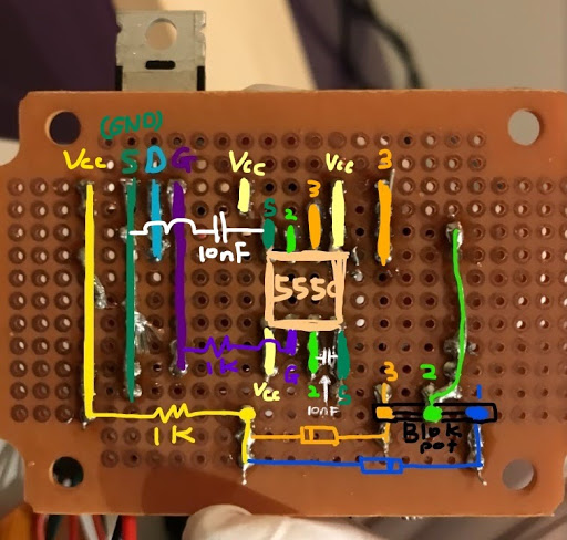
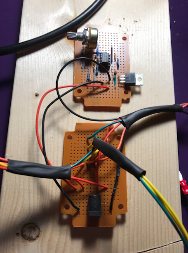
 10k Potentiometer, lead 1, 2, 3 from left to right
 This part of the motor driver circuit is different on breadboard and on PCB because, in the further steps, the motor will be controlled by an additional relay circuit (Explained later on), then it will go to the drain of the MOSFET.


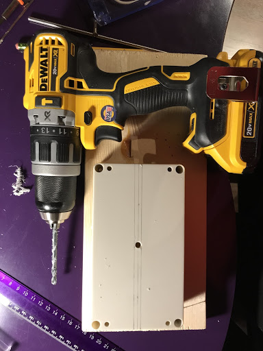
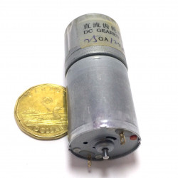
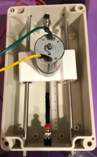
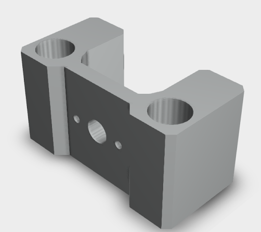 25GA motor base(3D designed by me file will be shared via link below)
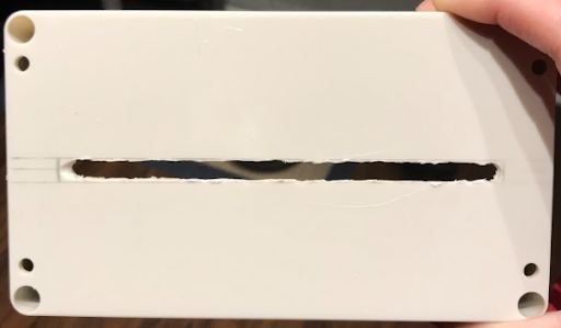
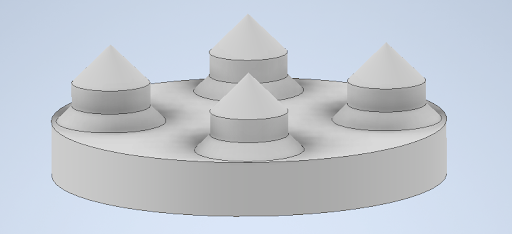
 Scratcher Plate(3D designed by me, file will be shared via link below)