.png)


How we will approach our orders going forward with the CUPW strike.
Blog categories
Search in blog
Latest posts
-
 About orders to be shipped out beginning November 15thRead more
 -
 Auto Brightness Adjusting LED StripRead more
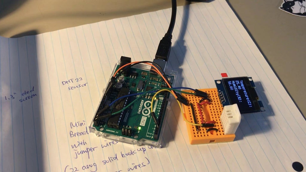
In this tutorial we will show you how to build an Auto Brightness Adjusting LED Strip
-
 Switching to Paper Bags in 2022Read more
Starting January 4th 2022, Lee's Electronic will start to phase out white plastic bags for packaging goods in store.
-
 Lee's Electronic x Bare Conductive Back to School GiveawayRead more
Lee's Electronic and Bare Conductive are collaborating once again to host a giveaway! This time one winner will win...
-
 Lee's Electronic X Bare Conductive Giveaway 2Read more
Lee's Electronic and Bare Conductive is collaborating to host another giveaway! This time we're giving away an...
Featured posts
-
About orders to be shipped out beginning November 15thHow we will approach our orders going forward with the CUPW strike.Read more
-
Auto Brightness Adjusting LED StripIn this tutorial we will show you how to build an Auto Brightness Adjusting LED StripRead more
-
Switching to Paper Bags in 2022Starting January 4th 2022, Lee's Electronic will start to phase out white plastic bags for packaging goods in store.Read more
-
 Electric Gear Motor Back ScratcherA step-by-step tutorial on how to build an electric gear motor back scratcher. This project introduces the concepts...Read more
 -
 Keyless Unlock SystemThis project is designed to keylessly lock and unlock the door by knocking. The device makes it convenient for the...Read more