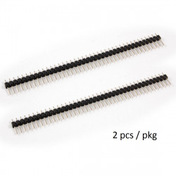
All pictures are for illustrative purposes only.
location_on 4131 Fraser St. Vancouver BC Get Directions
phone 604-875-1993 Call us
access_time Hours
| Monday - Friday | 9AM - 5:30PM |
| Saturday - Sunday & Holidays | Closed | See Holiday Hours |



| Overview |
|---|
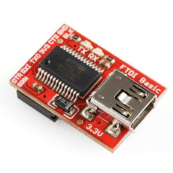
| The Arduino Pro Mini is a microcontroller board based on the ATmega168. It has 14 digital input/output pins (of which 6 can be used as PWM outputs), 6 analog inputs, an on-board resonator, a reset button, and holes for mounting pin headers. A six pin header can be connected to an FTDI cable or Sparkfun breakout board to provide USB power and communication to the board. |
| The Arduino Pro Mini is intended for semi-permanent installation in objects or exhibitions. The board comes without pre-mounted headers, allowing the use of various types of connectors or direct soldering of wires. The pin layout is compatible with the Arduino Mini. |
| There are two version of the Pro Mini. One runs at 3.3V and 8 MHz, the other at 5V and 16 MHz. |
| Summary | |
|---|---|
| Microcontroller | ATmega168 |
| Operating Voltage | 3.3V or 5V (depending on model) |
| Input Voltage | 3.35 -12 V (3.3V model) or 5 - 12 V (5V model) |
| Digital I/O Pins | 14 (of which 6 provide PWM output) |
| Analog Input Pins | 6 |
| DC Current per I/O Pin | 40 mA |
| Flash Memory | 16 KB (of which 2 KB used by bootloader) |
| SRAM | 1 KB |
| EEPROM | 512 bytes |
| Clock Speed | 8 MHz (3.3V model) or 16 MHz (5V model) |
| Power |
|---|
| The Arduino Pro Mini can be powered with an FTDI cable or breakout board connected to its six pin header, or with a regulated 3.3V or 5V supply (depending on the model) on the Vcc pin or an unregulated supply on the RAW pin. |
| The power pins are as follows: |
|
| Memory |
|---|
| The ATmega168 has 16 KB of flash memory for storing code (of which 2 KB is used for the bootloader). It has 1 KB of SRAM and 512 bytes of EEPROM (which can be read and written with the EEPROM library). |
| Input and Output |
|---|
| Each of the 14 digital pins on the Pro Mini can be used as an input or output, using pinMode(), digitalWrite(), and digitalRead() functions. They operate at 3.3 or 5 volts (depending on the model). Each pin can provide or receive a maximum of 40 mA and has an internal pull-up resistor (disconnected by default) of 20-50 kOhms. In addition, some pins have specialized functions: |
|
| The Pro Mini has 6 analog inputs, each of which provide 10 bits of resolution (i.e. 1024 different values). Four of them are on the headers on the edge of the board; two (inputs 4 and 5) on holes in the interior of the board. The analog inputs measure from ground to VCC. Additionally, some pins have specialized functionality: |
|
| There is another pin on the board: |
|
| Communication |
|---|
| The Arduino Pro Mini has a number of facilities for communicating with a computer, another Arduino, or other microcontrollers. The ATmega168 provides UART TTL serial communication, which is available on digital pins 0 (RX) and 1 (TX). The Arduino software includes a serial monitor which allows simple textual data to be sent to and from the Arduino board via a USB connection. |
| A SoftwareSerial library allows for serial communication on any of the Pro Mini's digital pins. |
| The ATmega168 also supports I2C (TWI) and SPI communication. The Arduino software includes a Wire library to simplify use of the I2C bus. To use the SPI communication, please see the ATmega168 datasheet. |
| Programming |
|---|
| The Arduino Pro Mini can be programmed with the Arduino software. |
| The ATmega168 on the Arduino Pro Mini comes preburned with a bootloader that allows you to upload new code to it without the use of an external hardware programmer. |
| You can also bypass the bootloader and program the ATmega168 with an external programmer. |
| Automatic (Software) Reset |
|---|
| Rather then requiring a physical press of the reset button before an upload, the Arduino Pro Mini is designed in a way that allows it to be reset by software running on a connected computer. One of the pins on the six-pin header is connected to the reset line of the ATmega168 via a 100 nanofarad capacitor. This pin connects to one of the hardware flow control lines of the USB-to-serial convertor connected to the header: RTS when using an FTDI cable, DTR when using the Sparkfun breakout board. When this line is asserted (taken low), the reset line drops long enough to reset the chip. The Arduino software uses this capability to allow you to upload code by simply pressing the upload button in the Arduino environment. This means that the bootloader can have a shorter timeout, as the lowering of the reset line can be well-coordinated with the start of the upload. |
| This setup has other implications. When the Pro Mini is connected to either a computer running Mac OS X or Linux, it resets each time a connection is made to it from software (via USB). For the following half-second or so, the bootloader is running on the Pro. While it is programmed to ignore malformed data (i.e. anything besides an upload of new code), it will intercept the first few bytes of data sent to the board after a connection is opened. If a sketch running on the board receives one-time configuration or other data when it first starts, make sure that the software with which it communicates waits a second after opening the connection and before sending this data. |
| Physical Characteristics | The dimensions of the Pro Mini PCB are approximately 0.7" x 1.3". |
|---|

