
location_on 4131 Fraser St. Vancouver BC Get Directions
phone 604-875-1993 Call us
access_time Hours
| Monday - Friday | 9AM - 5:30PM |
| Saturday - Sunday & Holidays | Closed | See Holiday Hours |


This item has been retired.
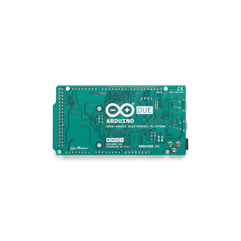
The Arduino MEGA ADK is a microcontroller board based on the ATmega2560. It has a USB host interface to connect with Android based phones, based on the MAX3421e IC. It has 54 digital input/output pins (of which 15 can be used as PWM outputs), 16 analog inputs, 4 UARTs(hardware serial ports), a 16 MHz crystal oscillator, a USB connection, a power jack, an ICSP header, and a reset button.
The MEGA ADK is based on the Mega 2560.
Similar to the Mega 2560 and Uno, it features an ATmega8U2 programmed as a USB-to-serial converter.
Revision 2 of the Mega ADK board has a resistor pulling the 8U2 HWB line to ground, making it easier to put into DFU mode.
Revision 3 of the board has the following new features:
| Microcontroller | ATmega2560 |
| Operating Voltage | 5V |
| Input Voltage (recommended) | 7-12V |
| Input Voltage (limits) | 6-20V |
| Digital I/O Pins | 54 (of which 15 provide PWM output) |
| Analog Input Pins | 16 |
| DC Current per I/O Pin | 40 mA |
| DC Current for 3.3V Pin | 50 mA |
| Flash Memory | 256 KB of which 8 KB used by bootloader |
| SRAM | 8 KB |
| EEPROM | 4 KB |
| Clock Speed | 16 MHz |
| USB Host Chip | MAX3421E |
| Length | 101.52 mm |
| Width | 53.3 mm |
| Weight | 36 g |

