

location_on 4131 Fraser St. Vancouver BC Get Directions
phone 604-875-1993 Call us
access_time Hours
| Monday - Friday | 9AM - 5:30PM |
| Saturday - Sunday & Holidays | Closed | See Holiday Hours |


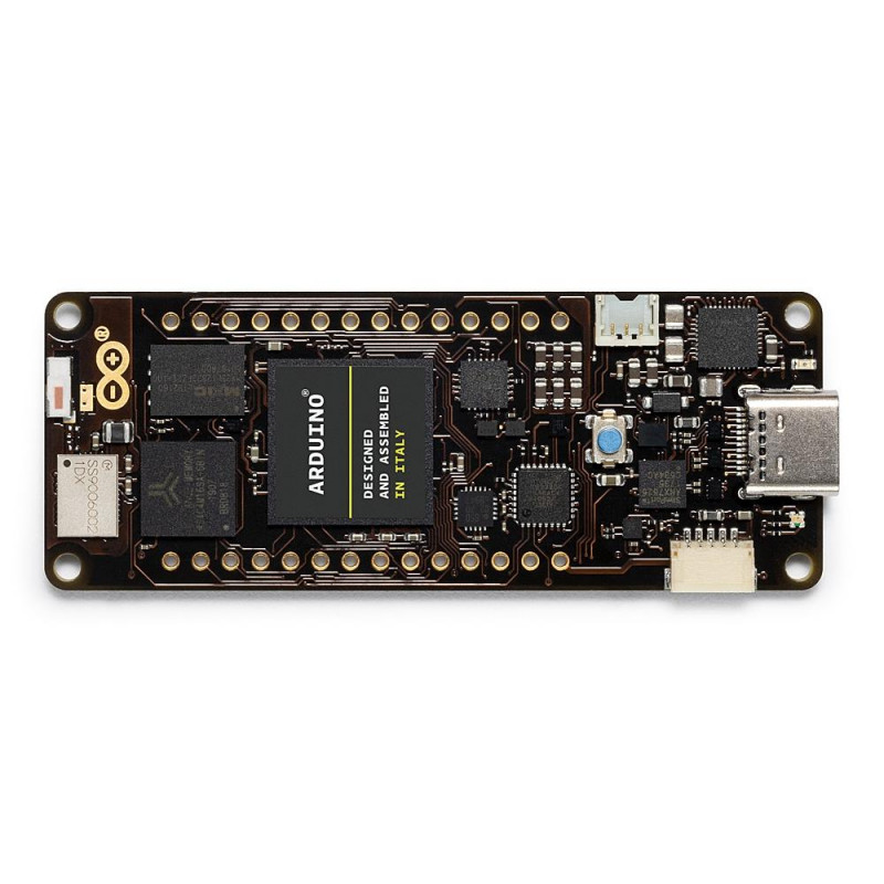
Portenta H7 simultaneously runs high level code along with real time tasks. The design includes two processors that can run tasks in parallel. For example, is possible to execute Arduino compiled code along with MicroPython one, and have both cores to communicate with one another. The Portenta functionality is two-fold, it can either be running like any other embedded microcontroller board, or as the main processor of an embedded computer.
Portenta can easily run processes created with TensorFlow™ Lite, you could have one of the cores computing a computer vision algorithm on the fly, while the other could be making low-level operations like controlling a motor, or acting as a user interface.
Use Portenta when performance is key, among other cases, we envision it to be part of:
· High-end industrial machinery
· Laboratory equipment
· Computer vision
· PLCs
· Industry-ready user interfaces
· Robotics controller
· Mission-critical devices
· Dedicated stationary computer
· High-speed booting computation (ms)
· Two Parallel Cores
H7's main processor is the dual core STM32H747 including a Cortex® M7 running at 480 MHz and a Cortex® M4 running at 240 MHz. The two cores communicate via a Remote Procedure Call mechanism that allows calling functions on the other processor seamlessly. Both processors share all the in-chip peripherals and can run:
· Arduino sketches on top of the Arm® Mbed™ OS
· Native Mbed™ applications
· MicroPython / JavaScript via an interpreter
· TensorFlow™ Lite
· Graphics Accelerator
Probably one of the most exciting features of the Portenta H7 is the possibility of connecting an external monitor to build your own dedicated embedded computer with a user interface. This is possible thanks to the STM32H747 processor's on-chip GPU, the Chrom-ART Accelerator™. Besides the GPU, the chip includes a dedicated JPEG encoder and decoder.
A new standard for pinouts
The Portenta family adds two 80 pin high density connectors at the bottom of the board. This ensures scalability for a wide range of applications by simply upgrading your Portenta board to the one suiting your needs.
On-board Connectivity
The onboard wireless module allows to simultaneously manage WiFi and Bluetooth® connectivity. The WiFi interface can be operated as an Access Point, as a Station or as a dual mode simultaneous AP/STA and can handle up to 65 Mbps transfer rate. Bluetooth® interface supports Bluetooth Classic and BLE. It is also possible to expose a series of different wired interfaces like UART, SPI, Ethernet, or I2C, both through some of the MKR styled connectors, or through the new Arduino industrial 80 pin connector pair.
USB-C Multipurpose Connector
The board's programming connector is a USB-C port that can also be used to power the board, as a USB Hub, to connect a DisplayPort monitor, or to deliver power to OTG connected devices.
Multiple options in one board
Order the default Arduino Portenta H7 (codename H7-15EUNWAD) that comes with:
· STM32H747 dual-core processor with graphics engine
· 8MB SDRAM
· 16MB NOR Flash
· 10/100 Ethernet Phy
· USB HS
· NXP SE050C2 Crypto
· WiFi/BT Module
· External Antenna
· DisplayPort over USB-C
If you need more memory, Portenta H7 can host up to 64 MByte of SDRAM, and 128 MByte of QSPI Flash. Order it with an external UFL connector for adding a higher-gain antenna to the board. Decide between crypo-chips from Microchip® and NXP. The board is highly customizable in volumes, ask our sales representatives for options.
The basic configurations you can consider to get the board to accommodate to your needs and budget are:
|
Option |
Description |
Option Codes |
|
SDRAM |
external SDRAM memory |
0 - None 1 - 8 MByte 2 - 16 MByte 3 - 32 MByte 4 - 64 MByte |
|
FLASH |
external QSPI Flash Memory |
0 - None 1 - 2 MByte (NOR) 5 - 16 MByte (NOR) 8 - 128 MByte (NAND) |
|
Ethernet |
10/100 Ethernet PHY |
0 - None E - Fitted |
|
HS USB |
High Speed USB PHY |
0 - None U - Fitted |
|
Crypto |
Crypto Chip |
0 - None M - ATECC608A N - SE050C2 |
|
Wireless |
Wireless Module |
0 - None W - Fitted |
|
Antenna |
Antenna option |
0 - None C - UFL connector |
|
Video |
Displayport output over USB-C |
0 - None D - Fitted |
Tech specs
The Arduino Portenta H7 is based on the STM32H747 microcontroller, XI series.
|
MICROCONTROLLER |
STM32H747XI dual Cortex®-M7+M4 32bit low power Arm® MCU (datasheet) |
|
RADIO MODULE |
Murata 1DX dual WiFi 802.11b/g/n 65 Mbps and Bluetooth 5.1 BR/EDR/LE (datasheet) |
|
SECURE ELEMENT (DEFAULT) |
NXP SE0502 (datasheet) |
|
BOARD POWER SUPPLY (USB/VIN) |
5V |
|
SUPPORTED BATTERY |
Li-Po Single Cell, 3.7V, 700mAh Minimum (integrated charger) |
|
CIRCUIT OPERATING VOLTAGE |
3.3V |
|
CURRENT CONSUMPTION |
2.95 μA in Standby mode (Backup SRAM OFF, RTC/LSE ON) |
|
DISPLAY CONNECTOR |
MIPI DSI host & MIPI D-PHY to interface with low-pin count large display |
|
GPU |
Chrom-ART graphical hardware Accelerator™ |
|
TIMERS |
22x timers and watchdogs |
|
UART |
4x ports (2 with flow control) |
|
ETHERNET PHY |
10 / 100 Mbps (through expansion port only) |
|
SD CARD |
Interface for SD Card connector (through expansion port only) |
|
OPERATIONAL TEMPERATURE |
-40 °C to +85 °C |
|
MKR HEADERS |
Use any of the existing industrial MKR shields on it |
|
HIGH-DENSITY CONNECTORS |
Two 80 pin connectors will expose all of the board's peripherals to other devices |
|
CAMERA INTERFACE |
8-bit, up to 80 MHz |
|
ADC |
3× ADCs with 16-bit max. resolution (up to 36 channels, up to 3.6 MSPS) |
|
DAC |
2× 12-bit DAC (1 MHz) |
|
USB-C |
Host / Device, DisplayPort out, High / Full Speed, Power delivery |
Pinout Diagram
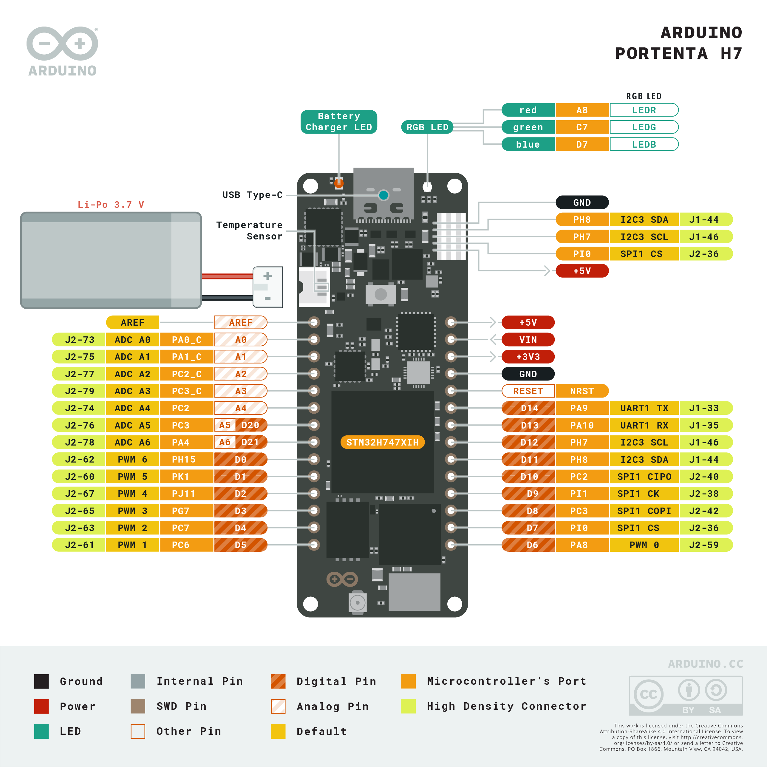
The Portenta H7 follows the Arduino MKR form factor, but enhanced with the Portenta family 80 pin high-density connector. Learn more about the board's pinout by reading the board's pinout documentation.

The Portenta H7 has an additional connector meant as an extension of the I2C bus. It's a small form factor 5-pin connector with 1.0 mm pitch. The mechanical details of the connector can be found in the connector's datasheet.
The I2C port, also referred to as the Eslov self-identification port within Arduino, comes with: SDA, SCL, GND, +5V, and an extra digital pin meant to send an alarm to the otherwise plain I2C devices connected to it. The pinout is shown in the following image:

If you are interested in designing your own modules for Arduino boards with this expansion port, the connector we suggest using is code: SHR-05V-S-B, also in the picture.
The Portenta H7 is a highly configurable design, it is possible to order boards with different configurations of memory, crypto chip, antenna, etc. These request will be channelled through Arduino's sales team and will require a minimum amount order. We recommend you try the default H7 configuration and if you need specific features for your solution, then contact us to discuss the terms.
