

location_on 4131 Fraser St. Vancouver BC Get Directions
phone 604-875-1993 Call us
access_time Hours
| Monday - Friday | 9AM - 5:30PM |
| Saturday - Sunday & Holidays | Closed | See Holiday Hours |


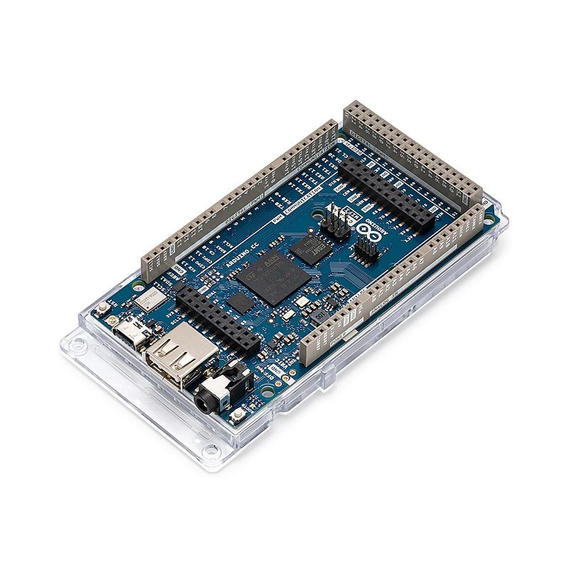
The Arduino GIGA R1 WiFi is designed for ambitious makers who want to step up their game. It levels the playing field for gamers, artists, sound designers and anyone coming to the tech world with big ideas on a budget – because it packs advanced features into an accessible component, with the same form factor as our popular Mega and Due.
Let’s break down all the powerful features of this board.
Microcontroller (STM32H747XI): This dual core 32-bits microcontroller allows you have two brain talking to each other (a Cortex®-M7 at 480 MHz and a Cortex®-M4 at 240 MHz) you can even run micropython in one and Arduino in the other.
Wireless communication (Murata 1DX): Whether you prefer Wi-Fi® or Bluetooth®, the GIGA R1 WiFi got you covered. You can even quickly connect to the Arduino IoT Cloud and keep track of your project remotely. And if you are concerned about the security of the communication, the ATECC608A keeps everything under control.
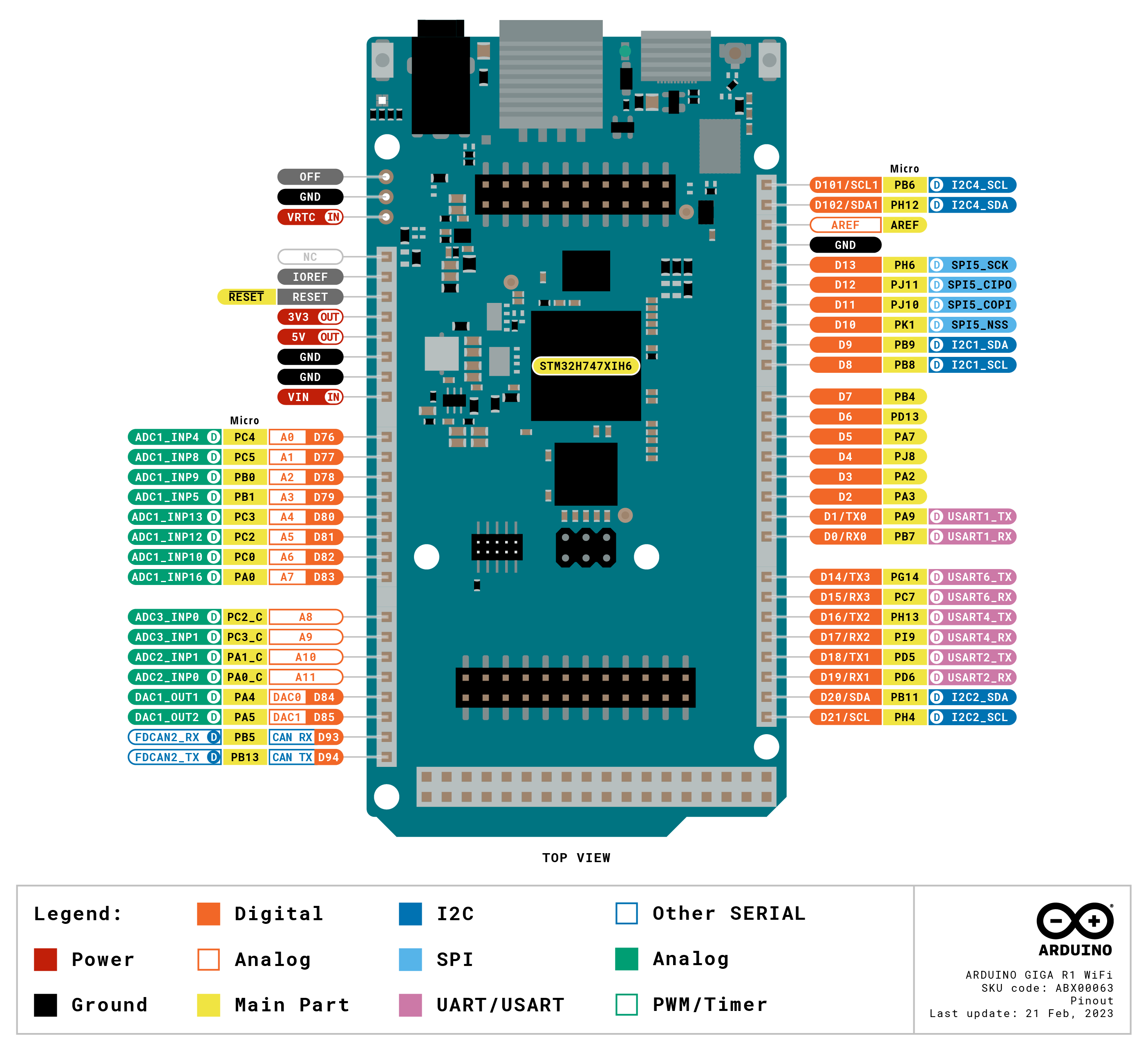
Hardware ports and communication: Following the legacy of the Arduino Mega and the Arduino Due, the GIGA R1 WiFi has 4 UARTs (hardware serial ports), 3 I2C ports (1 more than its predecessors), 2 SPI ports (1 more than its predecessors), 1 FDCAN.
GPIOs and extra pins: We wanted to keep the same form factor of the Mega and the Due, so you can easily adapt your custom made shields to the GIGA R1 WiFi (remember this board works at 3.3V though!) and we added extra headers to access extra pins, leaving the total count to 76 GPIO pins, and the best part, you can access them from underneath, so keep your project as it is and just think on how to expand it. Also, we added two new pins: a VRTC so you can connect a battery to keep the RTC running while the board is off and an OFF pin so you can shut down the board.
Connectors: The GIGA R1 WiFi has extra connectors on board which will facilitate the creation of your project without any extra hardware. This board has:
Higher voltage support: In comparison with its predecessors that support up to 12 volts, the GIGA R1 WiFi can handle a range of 6 to 24 volts.
| Board | Name | Arduino® GIGA R1 WiFi |
| SKU | ABX00063 | |
| Microcontroller | STM32H747XI dual Cortex®-M7+M4 32bit low power Arm® MCU (datasheet) | |
| Radio Module | Murata 1DX dual WiFi 802.11b/g/n 65 Mbps and Bluetooth® (datasheet) | |
| Secure Element | ATECC608A-MAHDA-T (datasheet) | |
| USB | USB-C® | Programming Port / HID |
| USB-A | Host (enable with PA_15) | |
| Pins | Digital I/O Pins | 76 |
| Analog input pins | 12 | |
| DAC | 2 (DAC0/DAC1) | |
| PWM pins | 12 | |
| Misc | VRT & OFF pin | |
| Communication | UART | Yes, 4x |
| I2C | Yes, 3x | |
| SPI | Yes, 2x | |
| CAN | Yes (Requires an external transceiver) | |
| Connectors | Camera | I2C + D54-D67 |
| Display | D1N, D0N, D1P, D0P, CKN, CKP + D68-D75 | |
| Audio Jack | DAC0, DAC1, A7 | |
| Power | Circuit operating voltage | 3.3V |
| Input voltage (VIN) | 6-24V | |
| DC Current per I/O Pin | 8 mA | |
| Clock Speed | Cortex® M7 | 480 MHz |
| Cortex® M4 | 240 MHz | |
| Memory | STM32H747XI | 2MB Flash, 1MB RAM |
| Dimensions | Width | 53 mm |
| Length | 101 mm | |

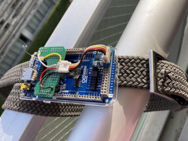
For those aged 65 and over, falls can be one of the most serious health concerns they face either due to lower mobility or decreasing overall coordination. Recognizing this issue, Naveen Kumar set out to produce a wearable fall-detecting device that aims to increase the speed at which this occurs by utilizing a Transformer-based model rather than a more traditional recurrent neural network (RNN) model. Because this project needed to be both fast and consume only small amounts of current, Kumar went with the new Arduino GIGA R1 WiFi due to its STM32H74XI dual-core Arm CPU, onboard WiFi/Bluetooth®, and ability to interface with a wide variety of sensors. After connecting an ADXL345 three-axis accelerometer, he realized that collecting many hours of samples by hand would be far too time consuming, so instead, he downloaded the SisFall dataset, ran a Python script to parse the sample data into an Edge Impulse-compatible format, and then uploaded the resulting JSON files into a new project. Once completed, he used the API to split each sample into four-second segments and then used the Keras block edit feature to build a reduced-sized Transformer model. The result after training was a 202KB large model that could accurately determine if a fall occurred 96% of the time. Deployment was then as simple as using the Arduino library feature within a sketch to run an inference and display the result via an LED, though future iterations could leverage the GIGA R1 WiFi's connectivity to send out alert notifications if an accident is detected. More information can be found here in Kumar's write-up.
Yes and yes, this board has no on board antenna however a u.FL antenna is provided in the box.
The camera adapter (J6 header) is a 20 pin adapter for Arducam cameras such as OV7675 and OV7670. For more information on how to use the camera visit the GIGA R1 WiFi Camera guide.
The difference between these two products are:
Any shield with the UNO, Mega or Due form factor that supports 3.3V is supposed to work with GIGA R1 WiFi but we recommend checking with the manufacturer.
The following shields (and their libraries) are officially compatible with GIGA R1 WiFi:
The GIGA R1 WiFi has two USB connectors. The USB-C® connector (USB0), next to the reset button and the u.FL antenna connector, is used for programming, serial communication and 5V power. The USB-A connector (USB1), next to the 3.5mm jack connector, is used as a USB host (not a programming port).

