.png)
All pictures are for illustrative purposes only.
|
Note |
label |
type |
parameters |
|
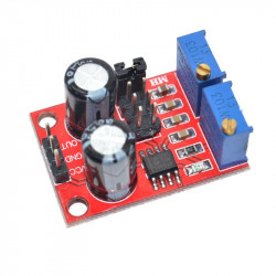
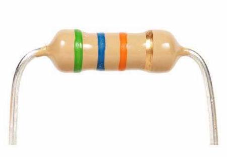
R1 |
resistor |
1K |
Regardless of the polarity |
|
R2 |
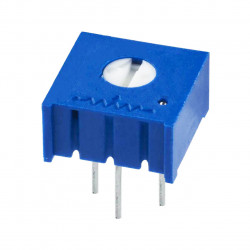
Adjustable resistance |
B503=50K |
(by screen printing layer) |
|
R3, R5,R6 |
resistor |
5.1K |
Regardless of the polarity |
|
R4 |
resistor |
330 |
Regardless of the polarity |
|
R7 |
Adjustable resistance |
B503=50K |
(by screen printing layer) |
|
R8 |
Adjustable resistance |
B104=100K |
(by screen printing layer) |
|
C1, |
Electrolytic capacitor |
100UF |
The positive short feet negative long feet |
|
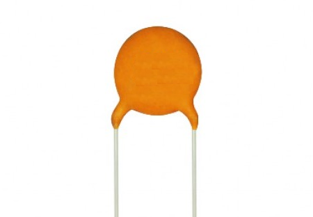
C2 |
non-polar capacitors |
104 |
Regardless of the polarity |
|
C3,C4 |
Electrolytic capacitor |
10UF |
The positive short feet negative long feet |
|
C5 |
non-polar capacitors |
105 |
Regardless of the polarity |
|
C6 |
non-polar capacitors |
473 |
Regardless of the polarity |
|
C7 |
non-polar capacitors |
222 |
Regardless of the polarity |
|
C8 |
non-polar capacitors |
101 |
Regardless of the polarity |
|
U1 |
IC |
XR2206 |
(by screen printing layer) |
|
JK1 |
DC POWER |
|
(by screen printing layer) |
|
J1 |
2PIN Jumper cap |
XM2.54 |
Regardless of the polarity |
|
J2 |
2PIN Jumper cap |
XM2.54 |
Regardless of the polarity |
|
P1 |
Signal wire terminal |
|
(by screen printing layer) |
|
J3 |
2*5P Jumper cap |
|
|
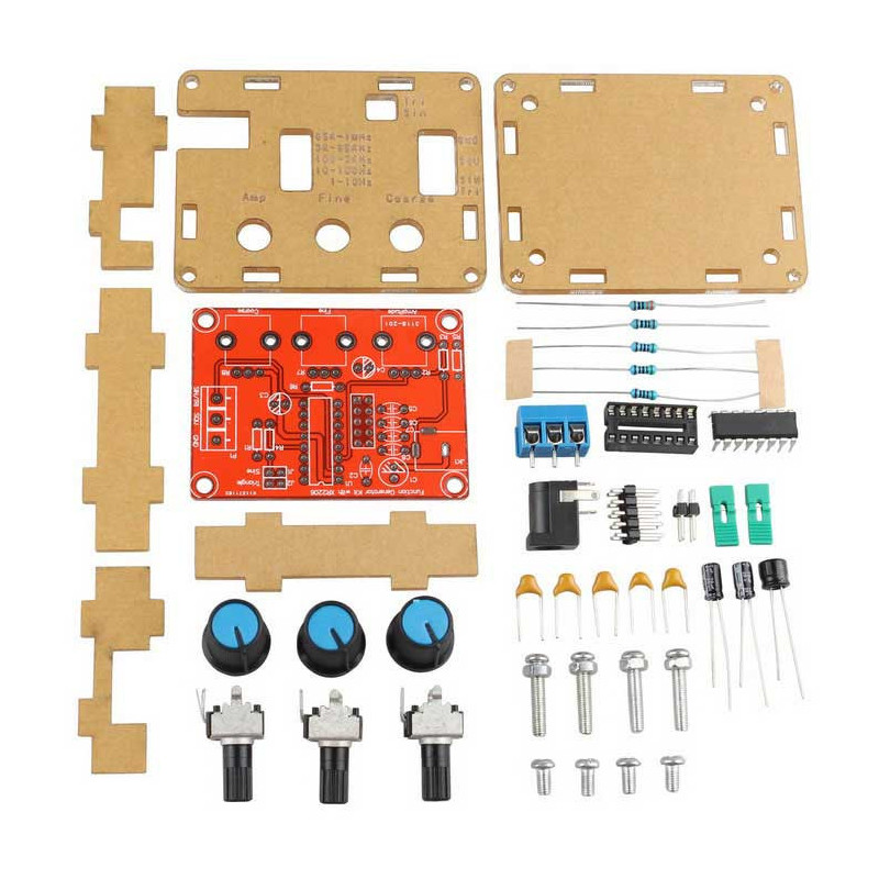
3The welding installation considerations, follow these steps:
1. The components are welding the front board, from low to high principles, namely the first low welding components, such as, capacitor, resistor, diode, etc.
2.Welding IC socket, terminal blocks, finally power socket, adjustable potentiometer.
3.The back with a diagonal cutting pliers to cut short the pins as far as possible
4Debugging steps:
1After completion of welding on IC, XR2206, pay attention to the direction of IC, insert the might damage the chip!
2. check the IC whether against, such as anti please timely correction.
3. Insert the power supply, power supply for 5.5 * 2.1 port, inside outside is negative polarity. For 9-12 v power supply voltage. The waveform may not be stable for more than 12 v
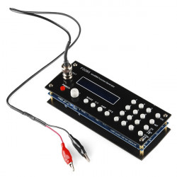
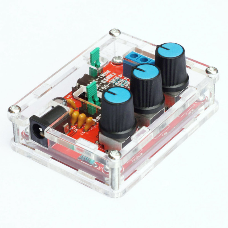
5Using the step
1. J1 jumper cap plug in, SIN/TRI blue terminals output sine wave (note J1, J2 can only insert one of)
2. J2 jumper cap plug in, SIN/TRI blue terminals output triangular wave (note J1, J2 can only insert one of)
3. SQU blue terminals output pulse
4. AMP : Sine wave, triangle wave amplitude adjustment
5. FINE : Frequency fine adjustment
6. Coarse : Frequency of coarse adjustment
6Schematic diagram of Function Generator