
location_on 4131 Fraser St. Vancouver BC Get Directions
phone 604-875-1993 Call us
access_time Hours
| Monday - Friday | 9AM - 5:30PM |
| Saturday - Sunday & Holidays | Closed | See Holiday Hours |


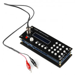
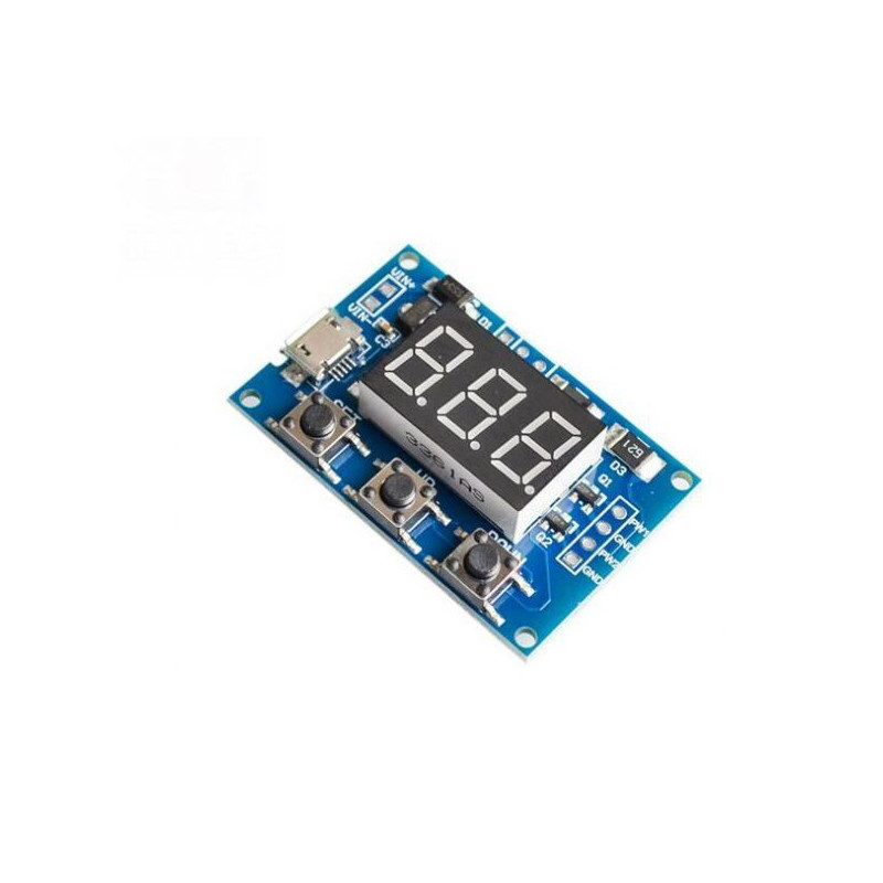
It is a kind of pulse frequency, square wave, pulse width modulation signal simulation circuit. It generates dual channel 1Hz to 150kHz pwm frequency square wave signal with adjustable duty ratio. Output frequency signal range is 1Hz-1kHz-150kHz (Customized input is available), the min. input frequency is 1Hz, max. frequency is 150KHz, its accordingly duty cycle range is 0-100. That pwm signal generator can be used to control and drive stepping motor. It can be used as square wave generator to provide square wave signal source for meters, sensor, MCU or other devices, be applied in light and speed control and adjustment.
PWM Generator Module Highlights:
>> 2-channel independent PWM output, frequency and duty cycle adjustable.
>> High accuracy, wide frequency range.
>> Serial ports communication is available.
>> Dimension: 4.3×2.9×0.9cm (1.69×1.14×0.35in).
PWM Generator Module Applications:
>> Square wave signal generator to output square wave signal.
>> Used as deriving module to control stepping motor.
>> Output adjustable pulse for MCU.
>> Output adjustable pulse to control PWM circuit or adjust light and speed.
PWM Generator Parameters:
1. Operating Voltage: 5-30VDC, support micro USB 5.0V power supply.
2. Frequency range: 1Hz-150KHz.
3. Frequency accuracy: about 2% in each frequency range.
4. Signal load capacity: output current is in 8-30mA.
5. Output amplitude: default 5V Vp-p (can be changed by adding external power supply).
6. Operating temperature range: -30~+70℃.
7. 3-type frequency range:
A. XXX (No decimal point): the min. unit is 1Hz, value range: 1Hz-999Hz.
B. XX.X (Decimal point in tens position): the min. unit is 0.1kHz, value range: 0.1KHz-99.9KHz.
C. X.X.X. (Decimal point in each digit): the min. unit is 1kHz, vaule range: 1KHz-150KHz.
E.g.: LED Display 100 indicates PWM output pulse 100Hz.
LED Display 54.1 indicates PWM output pulse 54.1KHz.
LED Display 1.2.4 indicates PWM output pulse 124KHz.
8. Value range of duty cycle: 0-100 . The three types of frequency value range are in the same duty cycle. All the settings is saved in power off state.
PWM Generator Parameters Setting:
1. Short press【Set】button, switch four parameters displayed: FR1: PWM1 Frequency, dU1: PWM1 duty cycle; FR2: PWM2 Frequency, dU2: PWM2 duty cycle. The LED flashing before setting it.
2. Press 【Up】,【Down】Buttons to revise the current value.
3. 2-channel PWM signal output, 3-type frequency range preset in the same duty cycle: Long press 【SET】button to switch the frequency range: XXX: Range 1Hz-999Hz; XX.X: Range 0.1Khz~99.9Khz; X.X.X: Range 1KHz-150KHz.
PWM Generator Serial Ports Control:
>> Communication standard: 9600bps.
>> Data bit: 8
>> Stop bit: 1
>> Check-sum bit: None
>> Stream control: None
PWM Generator Frequency & Duty Cycle Setting:
1. Set PWM Frequency:
“S1FXXXT”: Set PWM1 frequency into XXX HZ (001-999)
“S1FXX.XT”: Set PWM1 frequency into XX.X KHZ (00.1-99.9)
“S1F:X.X.X.T”: Set PWM1 frequency into XXX KHZ (0.0.1.-1.5.0.)
‘S1’: PWM1
‘S2’: PWM2
‘F’ : Frequency
‘D’ : Duty cycle
‘T’ : Stop bit indication
2. Set PWM Duty Cycle:
“S1DXXXT”: Set PWM1 duty cycle into XXX: (001-100)
“S2DXXXT”: Set PWM2 duty cycle into XXX: (001-100)
Setting successful, return: DOWN
Setting failed, return: FALL
PWM Signal Generator Kit Functions Description


