

location_on 4131 Fraser St. Vancouver BC Get Directions
phone 604-875-1993 Call us
access_time Hours
| Monday - Friday | 9AM - 5:30PM |
| Saturday - Sunday & Holidays | Closed | See Holiday Hours |


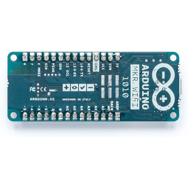
The MKR WiFi 1010 is a great choice for any beginner, maker or professional to get started with Internet of Things (IoT). Using the popular Arm® Cortex®-M0 32-bit SAMD21 processor, it also features the and the ECC508 crypto-chip for security. The board is part of the MKR family, where you can choose from a large variety of shields to build projects out of the box with minimal effort!
The powerful, low-power processor that is used in all MKR Family boards.
The ECC508 crypto chip makes sure your data remains secure and private, and can store up to 16 keys in an EEPROM array.
Please read: operating voltage is 3.3V
The microcontroller on the this board runs at 3.3V, which means that you must never apply more than 3.3V to its Digital and Analog pins. Care must be taken when connecting sensors and actuators to assure that this limit of 3.3V is never exceeded. Connecting higher voltage signals, like the 5V commonly used with the other Arduino boards, will damage the board.
Please read: black conductive foam
You should remove the black conductive foam from the board pins before usage. If you don't remove it, the board may behave erratically.
Tech specs
The Arduino MKR WiFi 1010 is based on the SAMD21 microcontroller.
| MICROCONTROLLER | SAMD21 Cortex®-M0+ 32bit low power ARM® MCU (datasheet) |
| RADIO MODULE | u-blox NINA-W102 (datasheet) |
| BOARD POWER SUPPLY (USB/VIN) | 5V |
| SECURE ELEMENT | ATECC508 (datasheet) |
| SUPPORTED BATTERY | Li-Po Single Cell, 3.7V, 1024mAh Minimum |
| CIRCUIT OPERATING VOLTAGE | 3.3V |
| DIGITAL I/O PINS | 8 |
| PWM PINS | 13 (0 .. 8, 10, 12, 18 / A3, 19 / A4) |
| UART | 1 |
| SPI | 1 |
| I2C | 1 |
| ANALOG INPUT PINS | 7 (ADC 8/10/12 bit) |
| ANALOG OUTPUT PINS | 1 (DAC 10 bit) |
| EXTERNAL INTERRUPTS | 10 (0, 1, 4, 5, 6, 7, 8,9, 16 / A1, 17 / A2) |
| DC CURRENT PER I/O PIN | 7 mA |
| CPU FLASH MEMORY | 256 KB (internal) |
| SRAM | 32 KB |
| EEPROM | no |
| CLOCK SPEED | 32.768 kHz (RTC), 48 MHz |
| LED_BUILTIN | 6 |
| USB | Full-Speed USB Device and embedded Host |
| LENGTH | 61.5 mm |
| WIDTH | 25 mm |
| WEIGHT | 32 gr. |
The MKR WiFi 1010 is open-source hardware! You can build your own board using the following files:
EAGLE FILES IN .ZIP SCHEMATICS IN .PDFFRITZING IN .FZPZ

