How we will approach our orders going forward with the CUPW strike.
Store address and hours
location_on 4131 Fraser St. Vancouver BC Get Directions
phone 604-875-1993 Call us
access_time Hours
| Monday - Friday | 9AM - 5:30PM |
| Saturday - Sunday & Holidays | Closed | See Holiday Hours |

-
 close
close -
CATEGORIES
-
-
-
-
-
-
-
-
-
-
-
-
-
Featured Item
-
-
-
-
-
-
-
more electrical devices
More electrical devices -
more electrical devices
More electrical devices
-
-
more electrical devices
More electrical devices -
more electrical devices
More electrical devices
-
-
Featured Items
-
more electrical devices
More electrical devices
-
-
-
-
-
-
-
-
Featured Item
-
-
-
-
-
-
-
Featured Items
-
-
-
-
-
-
-
-
Featured Items
-
-
-
Featured Items
-
-
-
-
-
-
-
-
-
-
-
Featured Items
-
-
-
-
-
-
-
-
-
Featured Items
-
-
-
-
-
-
featured
-
-
-
Featured Items
-
-
-
-
-
-
-
Featured Items
-
-
-
-
-
Featured Items
-
-
-
-
Featured Products
-
-
-
More Filaments
More Filaments
-
-
-
-
more electrical devices
More electrical devices
-
-
more electrical devices
More electrical devices
-
-
Electrical Devices
-
-
-
more electrical devices
More electrical devices
-
-
-
-
-
-
-
Featured Products
-
-
-
Featured Products
-
-
-
-
BRANDS
-
-
-
-
Brands/Manufacturers
-
-
Manufacturer 3
-
-
- PROJECTS
-
COMMUNITY
-
- SALE Sale
Binary Calculator
Objective:
To provide fundamental ideas of Boolean logic, gates, and electronics. To gain familiarity with using logic gates and binary systems. To compute the summation and subtraction of two 4-bit numbers
Target Audience:
Hobbyist, Enthusiastic High-Schoolers, College or University students.
Supplies:
Components Used*:
4 x 74LS08 TTL Quad 2-input AND gates PID:7243
4 x 4070 Quad 2-input XOR gates PID:7221
4 x 74LS32 Quad 2-input OR gates PID:7250
2 x 74LS04 Hex Inverter gates PID: 7241
22 AWG, Solid Core Wires PID: 224900
8 x ¼w 560 Resistor PID: 91447 (not needed if there are enough 1k resistors)
1 x 5V 1A Power Adapter Cen+ PID:1453 (*Higher Amperage or Center – can both be used)
5 x LED 5mm, Yellow PID: 551 (Color is irrelevant)
5 x LED 5mm, Green PID: 550 (Color is irrelevant)
1 x 2.1mm Jack to Two Terminals PID:210272 (#210286 can replace)
Optional:
Plier, PID: 10457 (Strongly Recommended)
*All numbers listed above correspond to Lee’s Electronic Components’ product ID
Step 1: Set Up the Power Supply (Adder)
Since we are going to be powering the whole circuit using a barrel jack power supply, we will need to separate the positive and ground. Note that we are working with the center positive power supply (+ inside and - outside), therefore + must come out as positive (in this case RED) and – must be ground (Black).
Connect the main power rail to each one of the vertical rails. So that the IC chips can easily be powered without wires going everywhere.
Step 2: Set Up the DIP Switch (Adder)
Two 4-position dip switches are placed on top of the 8-pin IC socket to ensure the firm grip of the board and it is then placed under the power rail. On the other side of the switch, we are going to place arbitrary value resistors* (I used 1k and two 560 in series)
Step 3: What Are These Resistors For???
They are called “Pull-Up” or “Pull-Down” resistors depending on the setup.
We are using these resistors because of something called “Floating Effect”.
Like the picture on the top right, when the switch is closed, the current flows with no problem. However, if the switch is opened, we have no idea to tell if the input is having enough voltages to determine the state and this effect is called the “Floating Effect”.
The logic states are represented by two voltage levels with any voltage below one level regarded as a logic 0, and any voltage above another level regarded as logic 1, but the pin itself cannot tell between whether input logic is 1 or 0 because of the statics or surrounding noises.
To prevent the floating effect, we use pull-up or down resistors like the diagram on the left.
Step 4: Set Up the Logic Gates (Adder)
Place the XOR, AND, OR, XOR, AND gates respectively (4070,74LS08,74LS32, 4070 and 74LS08). Connect the pin 14 of each chip to the positive rail and the pin 7 to the ground rail to activate the logic chips.
Step 5: Wire the Logic Gates (Adder)
Based on the schematic and appropriate datasheet, wire the gates accordingly. It is important to notice that the very first input carry bit is zero, thus it can simply be grounded.
Because we are making a 4-bit ADDER, the output carry will consistently be fed to the input carry of the other FULL ADDER until we get to the last unit.
*Note that the additional LED on pin 8 on the OR gate represents the last CARRY bit. It will only be lit up when the summation of two 4-bit number can no longer be represented with 4-bits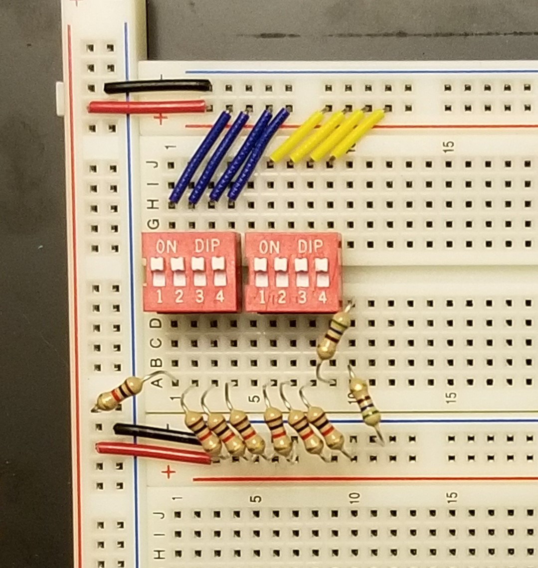
Step 6: Set Up the LEDs for the Output (Adder)
The output bit from the first FULL ADDER will directly be hooked up as the LSB (Least Significant Bit) of the resulting output.
The output bit from the second FULL ADDER will be hooked up to the second bit from the right of the resulting output, and so forth.
*Unlike the standard ¼ watt resistors we use to pull-down, the LEDs are polarized component and the direction of electron flows matter (because they are diodes). Therefore, it is important to assure that we connect the longer leg of the LED to be hooked up to the power and the shorter to the ground.
Lastly, the final CARRY bit is connected to pin 8 of the OR gate. Which represents the carry from the MSB (Most Significant Bit) and it will allow us to compute any two 4-bit binary numbers.
(it will only be lit up if the computed output exceeds 1111 in binary)
Step 7: Set Up the Power Supply (Subtractor)
The same power supply can be used to power up the SUBTRACTOR.
Step 8: Set Up the DIP Switch
Same as Adder.
Step 9: Set Up the Logic Gates (Subtractor)
Although a similar approach can be followed, subtractors require a NOT gate to be used before it feeds to the AND gate. Thus, in this case, I have placed the XOR, NOT, AND, OR, XOR, NOT and AND respectively (4070,74LS04, 74LS08,74LS32, 4070, 74LS04 and 74LS08).
Due to the limitation of the standard size breadboard having a length of 63 holes, the AND is connected on top.
As we did for the ADDER, connect the pin 14 of logic chips to the positive rail and the pin 7 to the ground to activate the chips.
Step 10: Wire the Logic Gates (Subtractor)
Based on the schematic and appropriate datasheet, wire the gates accordingly. It is important to notice that the very first input borrow bit is zero, thus it can simply be grounded.
Because we are making a 4-bit SUBTRACTOR, the output borrow will consistently be fed to the input borrow of the other SUBTRACTOR until we get to the last unit.
*Note that the additional LED on pin 8 on the OR gate represents the last borrow bit. It will only be lit up when the subtraction of two 4-bit numbers represents the negative number.
Step 11: Set Up the LEDS for the Output
The output bit from the first SUBTRACTOR will directly be hooked up as the LSB (Least Significant Bit) of the resulting output.
The output bit from the second SUBTRACTOR will be hooked up to the second bit from the right of the resulting output, and so forth.
Lastly, the final BORROW bit is connected to pin 8 of the OR gate. Which represents the BORROW to the MSB of the minuend. This LED is only turned on if the Subtrahend is greater than the Minuend. Since we are computing in binary, the negative sign does not exist; thus, the negative number will be computed in 2’s complement of its positive form. In this way, the subtraction of any two 4-bit numbers can be done.
Related posts
-
 Touch Switch Circuit With Mosfet
10/19/20174458 viewsThe simple touch switch LED circuit utilizes biasing characteristics of the MOSFET.Read more
 -
 Egg Timer
11/16/20182914 viewsThis project demonstrates the basics of digital logic, the characteristics of a NE555 timer, and demonstrates how...Read more
 -
 Arduino Piano Project
10/23/20173071 viewsThis is a piano board with eight push button switches that allows you to play one octave (Do Re Mi Fa So La Si Do)...Read more
 -
 Small AC to DC Converter
03/16/20183303 viewsThe small AC to DC Voltage Converter project uses four diodes to make one bridge rectifier to transfer AC power to DC...Read more
 -
 RF Remote Control Car
03/09/20174130 viewsThe RC car is a great project for all ages and it doesn’t require any programming. It uses simple integrated circuits...Read more


.png)
