How we will approach our orders going forward with the CUPW strike.
Store address and hours
location_on 4131 Fraser St. Vancouver BC Get Directions
phone 604-875-1993 Call us
access_time Hours
| Monday - Friday | 9AM - 5:30PM |
| Saturday - Sunday & Holidays | Closed | See Holiday Hours |

-
 close
close -
CATEGORIES
-
-
-
-
-
-
-
-
-
-
-
-
-
Featured Item
-
-
-
-
-
-
-
more electrical devices
More electrical devices -
more electrical devices
More electrical devices
-
-
more electrical devices
More electrical devices -
more electrical devices
More electrical devices
-
-
Featured Items
-
more electrical devices
More electrical devices
-
-
-
-
-
-
-
-
Featured Item
-
-
-
-
-
-
-
Featured Items
-
-
-
-
-
-
-
-
Featured Items
-
-
-
Featured Items
-
-
-
-
-
-
-
-
-
-
-
Featured Items
-
-
-
-
-
-
-
-
-
Featured Items
-
-
-
-
-
-
featured
-
-
-
Featured Items
-
-
-
-
-
-
-
Featured Items
-
-
-
-
-
Featured Items
-
-
-
-
Featured Products
-
-
-
More Filaments
More Filaments
-
-
-
-
more electrical devices
More electrical devices
-
-
more electrical devices
More electrical devices
-
-
Electrical Devices
-
-
-
more electrical devices
More electrical devices
-
-
-
-
-
-
-
Featured Products
-
-
-
Featured Products
-
-
-
-
BRANDS
-
-
-
-
Brands/Manufacturers
-
-
Manufacturer 3
-
-
- PROJECTS
-
COMMUNITY
-
- SALE Sale
Electric Gear Motor Back Scratcher

Project by Jeffrey Lin
Objective:
To develop a geared motor-driven horizontal back scratcher project aimed towards beginner-level electronic hobbyists, who are looking for some motor-related projects to start on. The aim is to provide an opportunity to learn about Pulse Width Modulation(PWM), geared motor, 555 timer IC, potentiometers, relay circuit design, soldering, prototyping circuitries on Printed Circuit Board(PCB), and 3D designing.
Introduction:
The goal of this scratcher machine is to vary the speed of the scratcher rotation and automate the direction of movement along a track. The scratcher mechanism is placed inside a long rectangular-shaped enclosure with a cut-out slot that allows for horizontal movement. The movement is created using a rack and pinion mechanism, which consists of a linear rotational motion of a gear along the geared rack.
Figure 1: Rack and Pinion Mechanism(Source: https://www.britannica.com/technology/rack-and-pinion)

Figure 2: Scratcher plate (Already 3D designed and can be downloaded and printed via shared link below)
Essential Items:
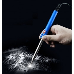
- Soldering Iron #10597
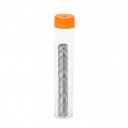
- 0.8mm Rosin Core Solder #10693
- 2x Printed Circuit Board #1059
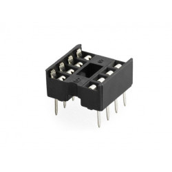
- 8-pin IC Socket #2137
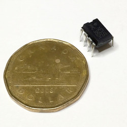
- NE555 timer IC #7307
- IRFZ48N N-channel MOSFET: #71204
- B10K Potentiometer: #71591
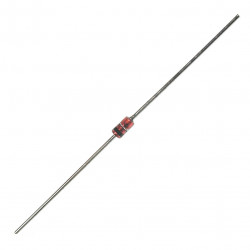
- 1N4148 fast switching diode: #7113
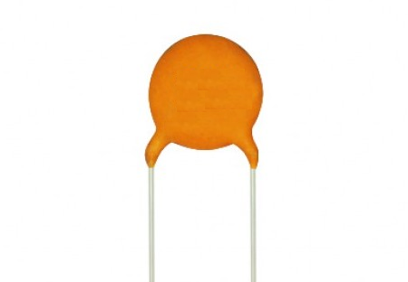
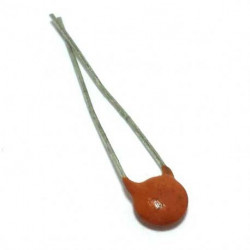
- 0.01uf ceramic capacitors 50V: #8180
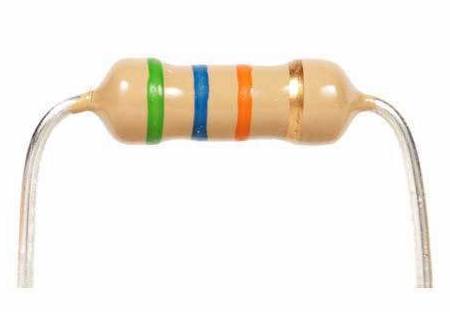
- 1K resistor #91901
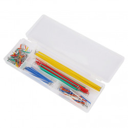
- Jumper wire set #10317
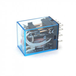
- RELAY, OMRON, MY4J 4PDT, 12VDC COIL, 5A: #3232
- RELAY SOCKET 14PIN PYF14A-E FOR MY-4: #3147
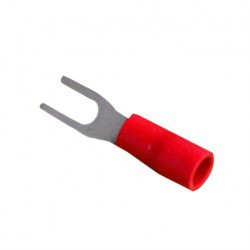
- Spade Connectors #6861
- 22awg hook up wire:
- DC barrel 2.1mm jack #2888
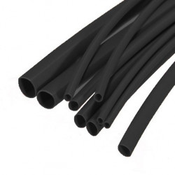
- Heat shrink #176025
- 4 ft of 6x22awg cable #211341
- Plastic Sealed Box #109481
- Push button N/C Momentary red P7-c: #3177
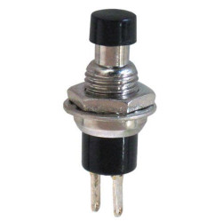
- Push button switch N/O momentary black: #315
- Geared motor 12V 100RPM 25GA: #41510
- 2 Linear Ball Bearing LM6UU #155661
- M3x8mm Screw #645
- M3 Washers #6059
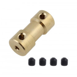
- Shaft Coupler #16392
- MINI shaft rod kit #16404
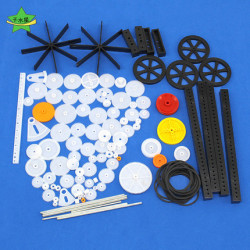
- Plastic Gear kit #15877
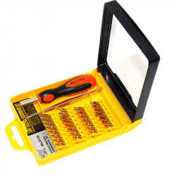
- Screw Driver #10859
- Utility Knife #104541
- Super Glue #43270
- Crimper #10563
- Stainless Steel Rod: https://www.homedepot.ca/product/paulin-3-16-x-36...
Related Parts
Step 1: Electronics
What is a PWM Signal?
A PWM signal is a digital square wave signal that produces either a high or a low output, and by changing the ratio between its high time and low time(also known as the duty cycles), different outputs are generated. For example, if a LED gets two minutes of 3V and two minutes of 0V, then on average during that total of four minutes the LED gets 1.5V.
For the 555 to output a square waveform, we will have to put it in its astable mode(one of the three modes of the 555 timer IC), which in this case, we will have to short the threshold(THRS) pin with the trigger(TRIG) pin.

Figure 3: 555 timer circuit astable mode wiring example (source: https://howtomechatronics.com)
To further explain the principle of the astable mode of the 555 timer circuit, the diagram above is an accurate demonstration of the basics of wiring in astable mode. Two resistors(R1 and R2) and a capacitor(C1) are required work with the 555 timer. The output is generated through an SR flip-flop(blue box in Figure 3) which takes input from two comparators(green triangles in Figure 3). The comparators take input from two variables:
- Threshold/Trigger pins(in this case shorted together) are connected to the positive side of the top comparator and the negative side of the bottom comparator(See inputs of the comparators in Figure 3)
- ⅔ of Vcc(8V) is connected to the negative side of the top comparator and ⅓ of Vcc(4V) is connected to the positive side of the bottom comparator (result of a voltage divider, refer to the vertical connection between Vcc and GND inside of the dashed line box in Figure 3)
How the Output Generates PWM


- Initially, the voltage at the Threshold/Trigger pins would slowly rise from 0 because of the charging of the capacitor(C1), which means the top comparator outputs 0 while the bottom comparator outputs 1(See Figure 4). This means Q output of the flip flop will be 1(See Figure 5), and the PWM signal will be high.
- The output will not change until the outputs of the two comparators are flipped. When the outputs are flipped, it means that the voltage at the threshold/trigger pins (also the voltage at the capacitor) has risen to a voltage greater than 8V (⅔ of Vcc). This will then also flip the output of the flip flop, bringing it low. The Q’ output(the opposite of the Q output) will then activate the transistor(See Figure 3), opening a path for the capacitor to discharge through R2 (See Figure 3).
- The discharge will lower the voltage at threshold/trigger pins and step 1 and 2 is repeated, bringing the signal high and low, thus creating a square wave.
How to Achieve Speed Control:
What is a Potentiometer?
- A potentiometer is a variable resistor that consists of three leads. The resistance between the first lead and the third lead.
-Resistance 1~3 = Resistance 1~2 + Resistance 2~3
-By turning the knob on the potentiometer, the resistance is altered between the first and second lead, as well as the resistance between the second and third lead.

Figure 6: Potentiometer and two diodes
To achieve speed variation, simply replace R2 in with a potentiometer and two diodes (Figure 6). The capacitor in Figure 3, instead of charging and discharging through R2, it will charge through D2 and the left side of the potentiometer and discharge through the right side of the potentiometer and D3. The resistance on the left and right side of the potentiometer determines the speed of charging and discharging. By adjusting the potentiometer, you adjust the duty cycle of the PWM signal that goes to the gate of MOSFET, thus changing the speed of the motor. (See Figure 7 below)

Figure 7: Astable 555 timer IC with potentiometer circuit schematic
Note: The diode D1 is not necessary for later steps of the project.
Step 2: Wiring Up the Breadboard
Wiring up a breadboard circuit before actually soldering a circuit on a PCB is always a good practice and can help you get a better understanding of the connections.

Note:
 10k Potentiometer, lead 1, 2, 3 from left to right
![]() IRFZ48N N-Channel MOSFET. G(Gate), D(Drain), S(Source)
IRFZ48N N-Channel MOSFET. G(Gate), D(Drain), S(Source)
![]() The symbol for 25GA 12VDC Geared Motor
The symbol for 25GA 12VDC Geared Motor
 This part of the motor driver circuit is different on breadboard and on PCB because, in the further steps, the motor will be controlled by an additional relay circuit (Explained later on), then it will go to the drain of the MOSFET.
Step 3: Soldering the Motor Driver onto a PCB
What you need:
- Soldering Iron #10597
- 0.8mm Rosin Core Solder #10693
- Printed Circuit Board #1059
- 8-pin IC Socket #2137
- NE555 timer IC #7307
- IRFZ48N N-channel MOSFET: #71204
- B10K Potentiometer: #71591
- 1N4148 fast switching diode x3: #7113
- 0.01uf ceramic capacitors 50V x2: #8180
- 1K resistor #91901
- Jumper wire set #10317
- Soldering Wick (Recommended)
Steps:
- Solder the 8-pin IC socket on to the centre of the board by placing it on top of the side that has no solder rings, then flip it around and melt the solder to the solder rings.

(the back side of the PCB after soldering the IC socket on) - Choose two different columns(or rows) on the board to be the Vcc and Gnd by soldering both ends of a short bit of solid wire across the column for future convenience.

- By following the schematic as well as the breadboard diagram in the last section, insert and solder each component onto the board. Make sure your connections are valid by performing continuity tests across connections.
- Plan your wiring beforehand, cut them into the right lengths so they do not have extra length hanging anywhere.
- Place the 555 IC in the socket as your final step


Figure 8: Completed motor driver circuit look from the front side
Figure 9: Completed motor driver circuit look from the back side, refer to the location of the MOSFET
Note:
- You can refer to the wiring done in Figure 8 and 9 if you run into confusion, remember to keep calm if you do make mistakes. Desoldering if necessary.
- IMPORTANT: Put aside three strands of hook up wires, one red and two blacks. Solder the red onto the Vcc(yellow), one black to the ground(green because the source is connected to the ground) and one black to the drain of the MOSFET. Leave the unsoldered end hanging(See Figure 10).

Figure 10: How the three hook up wires look like
Step 4: Latching Relay H-Bridge Circuit

Since the objective of the scratcher is to achieve automatic oscillation, an H-bridge will be applied to the motor. For the scratcher to move back and forth, it has to recognize the exact moment when it reaches the end of the rack and pinion mechanism.
Details: A relay can be interpreted as an on/off switch that is controlled by activating or deactivating a coil. A 12VDC 4PDT(4 Pole Double Throw) relay is then interpreted as four switches controlled by a 12V coil simultaneously(The relay is represented by the grey dash line box in the diagram above). SW5 and SW6 are the two push buttons that would be placed on the two ends of the scratcher enclosure. In the default state, 12V will only flow through SW2, the motor then to the ground via SW4. Since the default state is always the same, we can set the motor to initially rotate towards SW6(the normally open switch). As soon as the motor presses SW6, current flows through SW6 to the coil, activating it, switching the states of all four switches in the relay, which would reverse the direction of current through the motor(See wiring on the motor). Simultaneously, the current is also able to flow through SW5(normally closed switch), through SW1 and back to the coil, keeping the coil latched at the activated state(this is called “positive feedback”). The motor would eventually rotate till it reaches the other end of the scratcher enclosure, pressing SW5, disconnecting the current flowing into the coil, switching all the switches back to its default state, which would reverse the motor polarity once again, making it rotate in the default direction, towards SW6.
Setting up the latching relay circuit:

Figure 11: number coded relay pins (Note how pin 1, 3, 7, and 11 and not connected to anything, therefore only 10 out of the 14 pins are used)
What you need:
- RELAY, OMRON, MY4J 4PDT, 12VDC COIL, 5A: #3232
- RELAY SOCKET 14PIN PYF14A-E FOR MY-4: #3147
- Spade Connectors #6861
- Crimper
- Screwdriver
- Wire Stripper
- 22awg hook up wire:
- -Red #224012
- -Green #224015
- -Black #224010
- -Yellow #224014
- -Orange #224013
- Printed Circuit Board #1059
- Soldering Iron(same from the motor driver section)
- Solder (same from the motor driver section)
Steps:
- Prepare 10 pieces of stranded hook up wires, each about just less than 1 foot long:
- 3 Black
- 2 Yellow
- 2 Green
- 2 Orange
- 1 Red
- Strip one end of each wire, place the conductors(copper) inside of the holes of the spade connectors and crimp them tight with the top slot of the crimper. Make sure that the crimp is tight enough that you are not able to pull the wire away from the connectors when done.

- Place the relay onto the relay socket. There is only one way it would go in, so do not worry about making a mistake
- On a separate piece of PCB, choose three columns(or rows) and bridge the holes on that column or row with the same method mentioned in step 2 of soldering the motor driver

- These three “bridges” would be for the orange, green and yellow wires. Orange wires are the ones that have contact with the coil of the relay, while yellow and green are the plus and minus for the motor respectively.
- Among the 10 pieces of wires with spade connectors on one side of them, solder two orange, two yellow and two green into the three “bridges”(one colour to one “bridge”)
- After soldering, on the relay socket, insert and screw down the:
- Two yellows to pin 2 and pin 8
- Two greens to pin 4 and pin 6
- Two oranges to pin 9 and 13
(Note: the relay wiring is not yet completed at this step, it continues into the next section)
Step 5: Making the Power Board
What you need:
- The same PCB that you soldered the three “bridges” on
- DC barrel 2.1mm jack #2888
- A knife or a drill(anything that can potentially make the holes on the PCB slightly larger)
- Soldering Iron
- Solder
- 1 red hook up wire with the spade connector on it from step 1 of the last section
- 1 black hook up wire with the spade connector on it from step 1 of the last section
- 22awg hook up wire:
- Red #224012
- Green #224015
- Black #224010
- Yellow #224014
- Orange #224013
Steps:
- On the same PCB that you soldered the three “bridges” on, choose two more separate columns(or rows) to make them Vcc and Gnd using the same bridging method.

- Using a drill or a knife, make adjustments to the holes on the board so the DC barrel jack can sit nicely onto the board. Solder the Vcc and Gnd to the barrel jack accordingly(See Figure below)

Figure 12: Pinout for the DC Barrel jack - Prepare 5 pieces of hook up wires, each about half a foot long:
- 3 Black
- 2 Yellow
- 2 Green
- 2 Orange
- 1 Red
- Solder the 1 orange, 1 yellow and 1 green wire onto the same “bridge” that connects with wires that are the same color, then solder the 2 red wires to the Vcc bridge. Leave the other side of the wires hanging for now.
- Solder the red wire with the spade connector to the Vcc bridge, then insert and screw down the spade connector to pin 10 of the relay socket.
- Solder the black wire with the spade connector to the Gnd bridge, then insert and screw down the spade connector to pin 14 of the relay socket.
- See Figure 10, bring the red wire hanging on the motor driver board(in yellow circle in Figure 10) over and solder it to the Vcc “bridge”, then bring the black wire(in deep green circle in Figure 10) over and solder it to the Gnd “bridge”. Now your motor driver is connected to power!

Figure 13: Bottom view of the power board. - At the end of this section, you should have 9 connections in total(3 for each colour) on green, yellow and orange “bridges”. You should also have 4 connections on the Vcc bridge and 2 on the Gnd bridge
Step 6: Finishing Up With the Relay Wiring
What you need:
- The relay(should be on the socket with has 8 spade connections to it at this step)
- 2 remaining wires with spade connectors on them(Should be 2 blacks)
- Soldering Iron
- Solder
- Heat shrink #176025
- A lighter or heat gun
Steps:
- Solder and heat shrink 1 of the 3 remaining black spade connections to the only 1 hanging black wire on the motor driver board(in turquoise circle in Figure 10)(slide the heat shrink in first, shrink it with the lighter after soldering). Then insert and screw down the spade connection to pin 12 of the relay socket
- Insert and screw down the only remaining black spade connection to pin 5 of the relay socket and leave the other end hanging for now
- At the end of this section, you should have 6 wires free hanging:
- 1 yellow
- 1 green
- 1 orange
- 2 red
- 1 black hanging from pin 5 of the relay socket.
- Use heat shrink or other cable management to organize the wires


Note: if you do run into any sort of confusion, be sure to double-check that you have followed the steps in order.
Step 7: Making the Scratcher Box
What you need:
- 4 ft of 6x22awg cable #211341
- Plastic Sealed Box #109481
- 22awg hook up wire:
- Red #224012
- Green #224015
- Black #224010
- Yellow #224014
- Orange #224013
- Push button N/C Momentary red P7-c: #3177
- Push button switch N/O momentary black: #315
- Geared motor 12V 100RPM 25GA: #41510
- 2 Linear Ball Bearing LM6UU #155661
- Soldering Iron
- Solder
- Heat Shrink #176025
 25GA motor base(3D designed by me file will be shared via link below)
 Scratcher Plate(3D designed by me, file will be shared via link below)
- M3x8mm Screw #645
- M3 Washers #6059
- Shaft Coupler #16392
- MINI shaft rod kit #16404
- Plastic Gear kit #15877
- Screw Driver
- Utility Knife #104541
- Super Glue #43270
- Drill for the plastic enclosure
- Two rods, preferably stainless steel. The diameter needs to be less than 6mm(has to fit inside of the bearings). The length needs to be greater or equal to 17.0mm.
Note: The rod I used was a 3/16” diameter Stainless Steel rod from Home Depot, then it was cut into the right lengths by a metal saw.
Steps:
- Cut and strip about 3 inches of the 6x22awg wire. The 6 colours should be red, black, yellow, green, white, brown.
- As described in step 3 of the last section, there would be 6 wires freely hanging from the PCB and relay.
- Among the 6 wires, solder and heat shrink from the PCB/relay to one end of the 6x22awg wire:
- Yellow to yellow
- Green to Green
- Red to Red
- Red to White
- Black from Pin 5 of the relay socket to Black
- Orange to Brown
- Prepare 1.5ft of 22awg hook up wire in:
- Yellow
- Green
- 2 Red(2 pieces of 1.5ft)
- Orange
- Black
- On the black(N/O) push button, solder and heat shrink one red and orange wire.
- On the red(N/C) push button, solder and heat shrink one red and black wire.
- On the 25GA geared motor, solder and heat shrink the yellow wire onto the terminal with a red dot above it, then solder the green wire onto the other terminal.
- On the 3D printed motor bracket, mount and screw down the motor, make sure the motor does not wiggle from its base
- On the 3D printed motor bracket, insert the LM6UU linear ball bearings into the holes on the sides of the bracket.
- Underneath the motor bracket, insert the shaft coupler
- Find a 3mm shaft rod from the rod kit #16404, and the smallest plastic gear that could tightly fit into the shaft from the gear kit #15877. Insert the gear into the shaft rod.
- On the bottom of the plastic enclosure, drill a slot in the center that’s about 14cm long and 1cm in width


- Use a utility knife to smooth out the edges of the slot until it becomes a clean slot


- Insert the gear and shaft rod into the bottom end of the shaft coupler underneath the motor bracket(the gear should stick to the bottom of the coupler). Tightly fix the set screws on the coupler.
- On both sides of the enclosure, drill three holes(two at where the rods are, one in a green circle for the switches) as instructed with the dimensions below.

Note: Do be careful with the dimensions because it does affect how smoothly the rods slide in the bearings. Make sure the drill straight into the holes. - Slide the rods through the holes and the bearings as seen below. (Do not glue anything yet)

- If the motor bracket does slide on the track smoothly, find Gear Rack from gear kit #15877 and place it beside the gear so the teeth of the gear bite into the rack. Use a pencil to mark where the rack is sitting.
- Remove everything from the enclosure, then super glue the rack onto the bottom of the enclosure. The gear should then rotate smoothly against the rack as seen below

- Super Glue the rods into its place, the entire motor bracket should be locked in place because of the lock-in mechanism provided by the gear and rack. Then insert and super glue the push buttons into the holes as seen below.

Note: if your motor bracket does not get locked completely by the rack, then it is advised that you double-check on the tightness of the shaft coupler set screws. - At the end of this section, you should have 6 wires hanging freely from the scratcher box:
- Yellow and Green from the motor
- Red and Orange from the black push button
- Red and Black from the red push button
- Among the 6 wires, solder and heat shrink the other end of the 6x22awg wire:
- Yellow to yellow
- Green to Green
- Red to Red
- Red to White
- Black to Black
- Orange to Brown
- Insert the 3D printed scratcher plate onto the shaft that comes out at the bottom of the slot Note: Sand the tips of the scratcher down for a little with a piece of sandpaper
- Congratulations! You are finished! Now plug in any 12V supply into the barrel plug and enjoy the scratch!
Video Demonstration
Wrapping Up:
- By gluing a piece of sponge at the bottom of both of the two legs of the bracket and making it contact the bottom of the enclosure, the movement of the motor bracket can be better secured.
- For aesthetic purposes, you can cut the original clear top of the enclosure into the right sizes then screw the top back in its place.
- You can also add a handle of your own design onto the scratcher box if desired. You can also add an aesthetic-looking turn knob onto the potentiometer.
- For managing the 3D designed parts, Autodesk Inventor is an intuitive tool to use. If you are a student, you can get a renewable 1-year free pass to use it via this link: (https://www.autodesk.com/education/edu-software/overview?sorting=featured&page=1)
- You can alter the design of the 3D designed parts to your own discretion on Inventor. Try your best not to alter the dimensions though as it will affect the assembly negatively.
Why use a 555 timer IC(PWM) if you can just simply use a potentiometer to control the voltage?
- It’s the difference in power dissipation.
- By using the 555 timer IC chip to generate PWM waves, you are constantly switching between connecting and disconnecting the power source.
Related products
-
PUSH BUTTON SWITCH N/O MOMENTARY BLACK
Price: 0,90 CA$ -
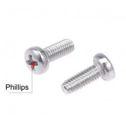
SCREW M3X8MM 10PCS
Price: 1,10 CA$ -
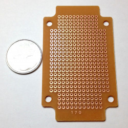
PRINTED CIRCUIT BOARD 170
Price: 1,50 CA$ -
-
-
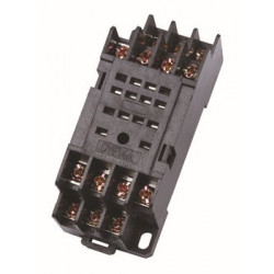
RELAY SOCKET 14PIN PYF14A-E FOR MY4
Price: 4,50 CA$ -
PUSH BUTTON, N/C, MOMENTARY, RED, P7-C (7mm Hole)
Price: 0,95 CA$ -
RELAY, OMRON, MY4J 4PDT, 12VDC COIL, 5A
Price: 7,50 CA$ -
-
SPADE CONNECTOR, SV1.25-3, NO.4 (3.2mm) STUD, 22-16AWG, 10PCS/PKG
Price: 1,20 CA$SPADE CONNECTOR NO.4 SV1.25-3 10PCS -
DIODE FAST SWITCHING 1N4148 4PCS
Price: 0,60 CA$ -
IC NE555P TIMER CIRCUIT
Price: 0,90 CA$The super popular 555 timing circuit. Used in a variety of timer, pulse... -
CERAMIC CAP 50V 0.01UF (103) 10PCS
Price: 0,80 CA$ -
BREADBOARD JUMPER WIRE SET MB-900 (0165-011-000)
Price: 8,50 CA$ -
TOOL, RT-301H INSULATED TERMINAL CRIMPER
Price: 32,50 CA$ -
SOLDERING IRON,GAOJIE,40W,NO640
Price: 12,95 CA$GaoJie 640 40W 120V soldering iron for small hobby soldering work. -
-
-
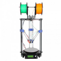
DELTA ROSTOCK MINI G2S 3D PRINTER KIT
Price: 600,00 CA$This Rostock mini G2s is a companion piece of our new upgraded delta 3D... -
-
-
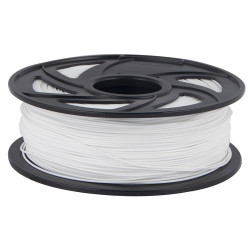
ANET 3D PRINTER FILAMENT PLA 1.75MM 1KG WHITE
Price: 29,50 CA$ -
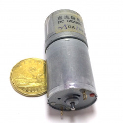
GEAR MOTOR 12V 130RPM 25GA
Price: 15,00 CA$ -
SPEAKER GLUE, WHITE, 30ML
Price: 8,00 CA$ -
POWER MOSFET IRFZ-48 N-CHANNEL 60V 50A 0.018OHM
Price: 3,00 CA$ -
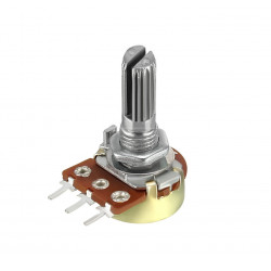
POTENTIOMETER, LINEAR B10K, 20MM SPLIT KNURLED SHAFT, PCB, 16MM
Price: 1,50 CA$POTENTIOMETER 10K(B) -
-
-
PLASTIC SEALED BOX 158X90X60MM W/ CLEAR TOP
Price: 12,40 CA$PLASTIC SEALED BOX 155X88X60MM W/ CLEAR TOP -
-
-
MULTICORE CABLE 6X22AWG (RVVP) UL2464 SHIELDED - PER FOOT
Price: 1,25 CA$CABLE 6X22AWG SHIELDED CABLE RVVP 300/300V JB8734.5-1998 PVC BLACK JACKETED... -
HOOK UP WIRE UL1007 22AWG BLACK - 10FT/PKG (0.16mmx17) 300ac -20/80c
Price: 1,40 CA$HOOK UP WIRE 22AWG BLACK - 10FT/PKG -
HOOK UP WIRE UL1007 22AWG RED - 10FT/PKG (0.16mmx17) 300ac -20/80c
Price: 1,40 CA$HOOK UP WIRE 22AWG RED - 10FT/PKG -
HOOK UP WIRE UL1007 22AWG ORANGE - 10FT/PKG (0.16mmx17) 300ac -20/80c
Price: 1,40 CA$HOOK UP WIRE 22AWG ORANGE - 10FT/PKG -
HOOK UP WIRE UL1007 22AWG YELLOW - 10FT/PKG (0.16mmx17) 300ac -20/80c
Price: 1,40 CA$HOOK UP WIRE 22AWG YELLOW - 10FT/PKG -
HOOK UP WIRE UL1007 22AWG GREEN - 10FT/PKG (0.16mmx17) 300ac -20/80c
Price: 1,40 CA$HOOK UP WIRE 22AWG GREEN - 10FT/PKG
Related posts
-
 Touch Switch Circuit With Mosfet
10/19/20174437 viewsThe simple touch switch LED circuit utilizes biasing characteristics of the MOSFET.Read more
 -
 Egg Timer
11/16/20182898 viewsThis project demonstrates the basics of digital logic, the characteristics of a NE555 timer, and demonstrates how...Read more
 -
 Arduino Piano Project
10/23/20173032 viewsThis is a piano board with eight push button switches that allows you to play one octave (Do Re Mi Fa So La Si Do)...Read more
 -
 Small AC to DC Converter
03/16/20183289 viewsThe small AC to DC Voltage Converter project uses four diodes to make one bridge rectifier to transfer AC power to DC...Read more
 -
 RF Remote Control Car
03/09/20174102 viewsThe RC car is a great project for all ages and it doesn’t require any programming. It uses simple integrated circuits...Read more


.png)
