.png)


All pictures are for illustrative purposes only.
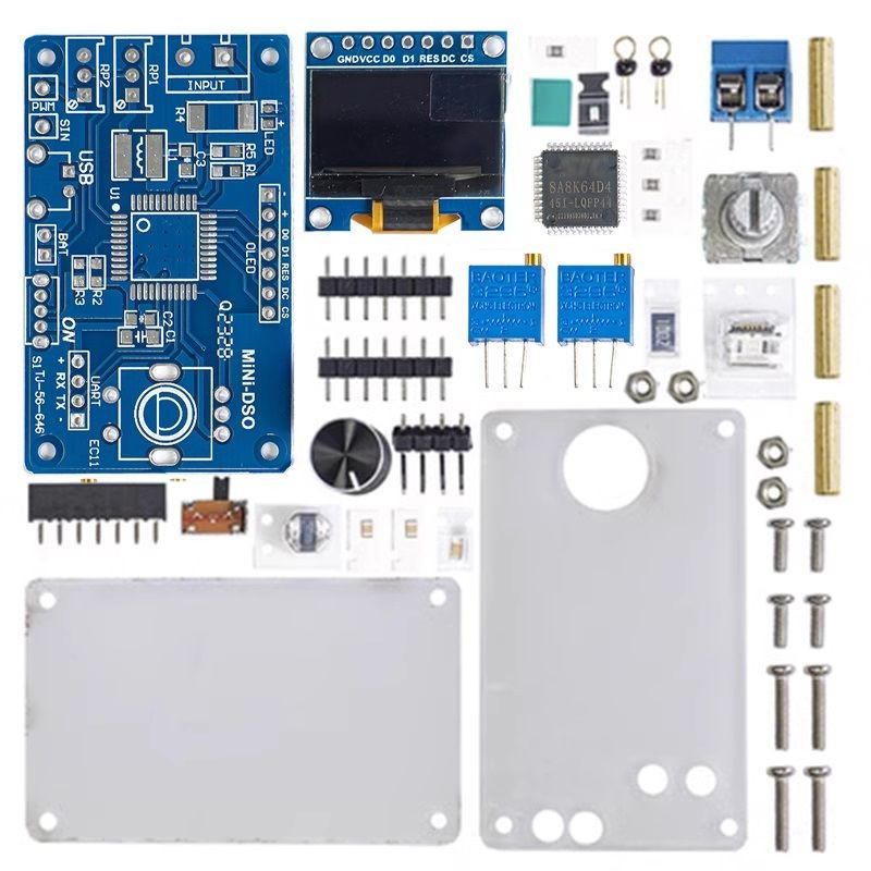
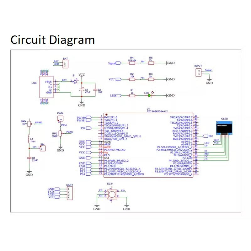
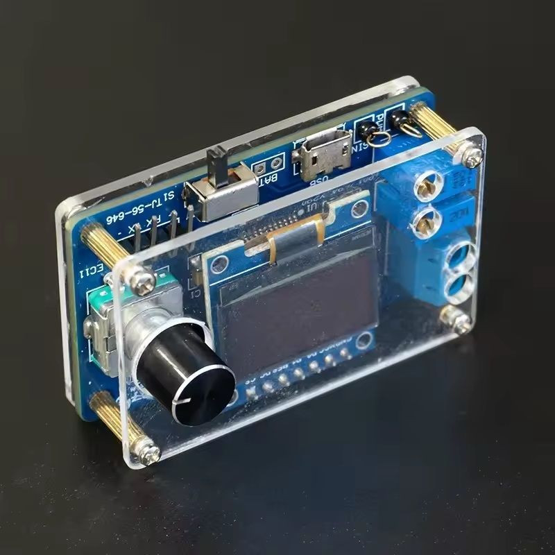
This is a simple oscilloscope made with STC8A8K microcontroller. It only requires a few components and is easy to assemble. Functions can cover simple measurements. This kit aims to build a basic oscilloscope model using the simplest principles and as little hardware as possible. The source code is easy to understand. While using the product, it is also very suitable for interested electronics enthusiasts to study and research.
PRODUCT PARAMETERS
*Trigger level: For repetitive signals, the trigger level enables stable display. For single shot signals, the trigger stage can be captured.
*Trigger slope: The trigger slope determines whether the trigger point is on the rising edge or falling edge of the signal.
Trigger Modes:
*Auto mode: continuous scanning. Click an encoder to stop or run sampling. If triggered, the waveform will appear on the display and the trigger position will be placed in the center of the graph. Otherwise, the waveform will scroll irregularly and display "Fail".
*Normal mode: After pre-sampling is completed, the signal can be input. If triggered, the waveform is displayed on the display, waiting for a new trigger. If there are no new triggers, the waveform will be retained.
*Single mode: After pre-sampling is completed, the signal can be input. If triggered, the waveform is displayed and sampling stops. The user needs a single point encoder to start the next sample.
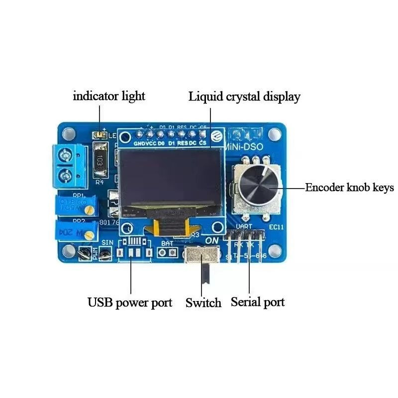
*In normal mode and single mode, confirm that the trigger level has been adjusted correctly, otherwise the waveform will not be displayed on the display *Indicator light: Usually the indicator light is on to indicate that sampling is running.
*Save settings: When exiting the setting interface, all parameters of the setting interface and main interface will be saved in EEPROM.