

location_on 4131 Fraser St. Vancouver BC Get Directions
phone 604-875-1993 Call us
access_time Hours
| Monday - Friday | 9AM - 5:30PM |
| Saturday - Sunday & Holidays | Closed | See Holiday Hours |


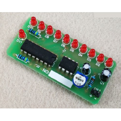
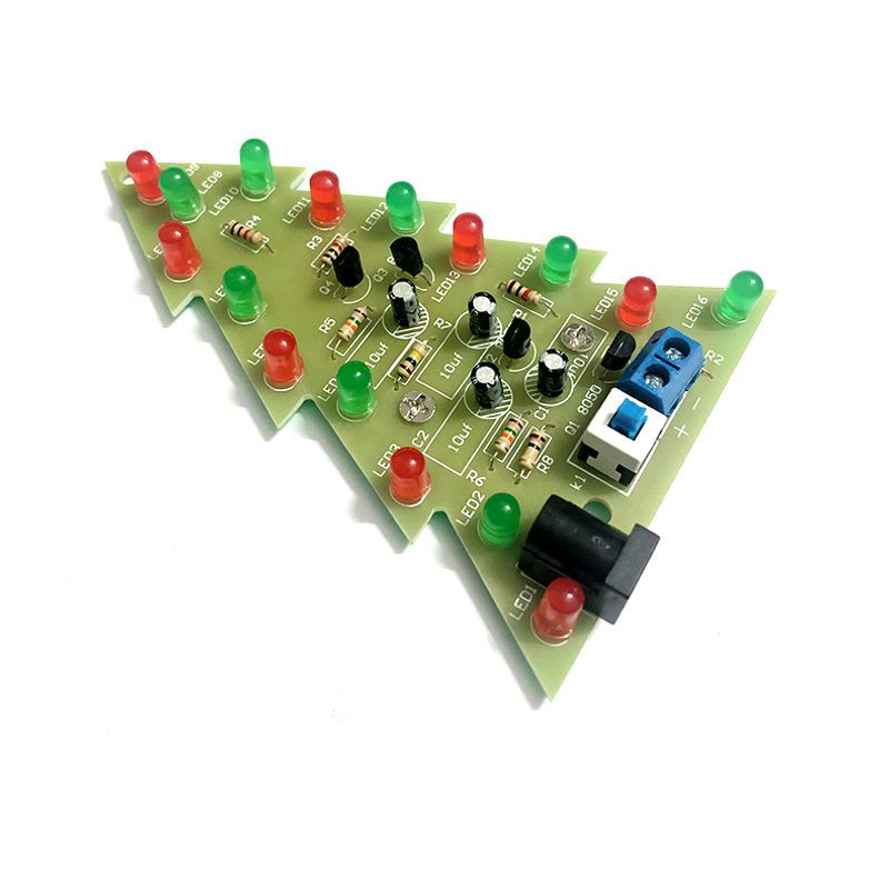
Looking for a small kit to play with? This kit is unassembled so it requires one to put it together by soldering. This is perfect for the christmas holidays and to practice soldering with.
Additional Info
1. There are silk screen logos of various components printed on the PCB board. Please solder according to the silk screen logo.
2. Resistors have no direction, but have different negative values. Please distinguish them when soldering.
3. The long leg with legs is positive (+), and the short leg is negative (-); pay attention to the silk screen direction on the PCB board when soldering;
4. When connecting the power cord to the terminal block, pay attention to distinguish the positive and negative poles, and do not connect them in reverse.
5. The welding sequence is from low to high, from small to large, and from inside to outside.
6. The soldering temperature of the soldering iron is 320°-380°, and the soldering is about 3-5 seconds. Do not solder for a long time! To avoid damaging the ground wire of the circuit board.
7. The circuit board logo VCC is positive and GND is negative.
8. Pay attention to static electricity and the power supply size of the product to avoid burning the circuit board and components.
This circuit is an oscillating circuit generated in a cyclic form.
1. After the first charge, capacitors C1 and C4 are fully charged.
2. Capacitors C2 and C3 continue to charge.
3. When transistors Q1 and Q4 are turned on, capacitors C1 and C4 are discharged.
4. After capacitors C2 and C3 are fully charged, transistors Q1 and Q4 cut off the current, and capacitors C1 and C4 are charged again.
5. Transistors Q2 and Q3 are turned on and capacitors C2 and C3 are discharged. By analogy, the speed of the flashing light is the oscillation frequency, and the frequency value is determined by the value of resistor R and capacitor C.
Note: This kit does NOT include batteries.

