.png)

All pictures are for illustrative purposes only.
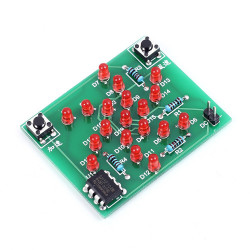
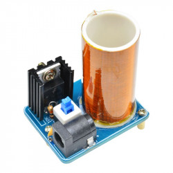
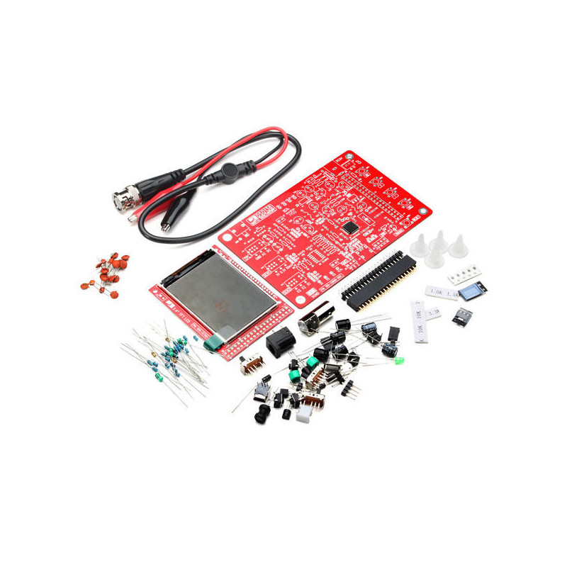
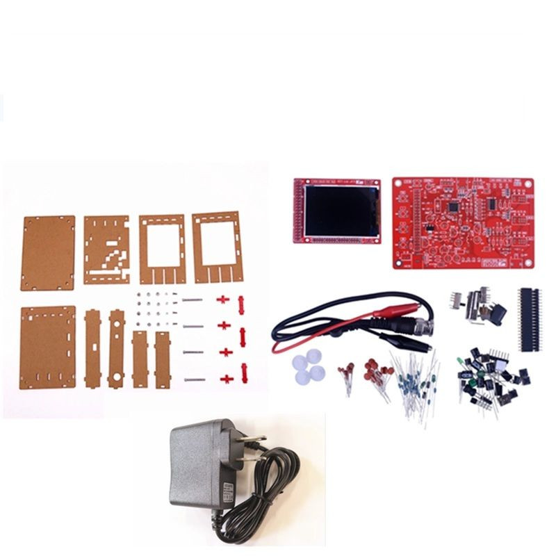
This DIY kit was designed for both training and tool of development use. The design is clear and easy to understand. Users will have more understanding of oscilloscope during soldering the kit and own a very useful oscilloscope which is made by their own hand
Description:
The DS0138 oscilloscope kit is a kit specifically designed for electronic professional teaching and training. It uses an ARM Cortex-M3 processor and a color TFT screen. It has the characteristics of simple and reliable circuits, moderate difficulty in production, and a high production success rate. The DS0138 kit highlights the characteristics of the oscilloscope circuit, allowing students to learn practical production skills while gaining a deep understanding of the structure and principle of the oscilloscope. The oscilloscope itself has good practicality.
After completing the production, students also obtain a useful tool, which is of great help to the future learning of electronic technology. It is worth noting that the oscilloscope is also a STM32 microcontroller (STM32 F103C8) development experiment board with a color TFT LCD display.
Features of the DS0138 oscilloscope production kit:
It is oriented to electronic production training, with complete and detailed information, including circuit diagrams, production instructions, instructions for use, troubleshooting methods, etc., and a high production success rate.
There are various types of components, which are suitable for students to carry out component identification, direct plug-in component welding, and patch component welding training.
Students can obtain a practical tool while making it, which can effectively observe and measure the signal waveforms in many occasions such as audio, video synchronization, low-frequency switching power supply, infrared reception and transmission, etc., which can increase learning interest and improve learning effect.
The kit uses ARM Cortex-M3 processor (STM32F103C8) and includes a 2.4-inch color TFT display, which can be used as an ARM development test board. The circuit is simple, reliable and inexpensive.
Characteristics: