.png)
All pictures are for illustrative purposes only.
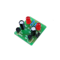
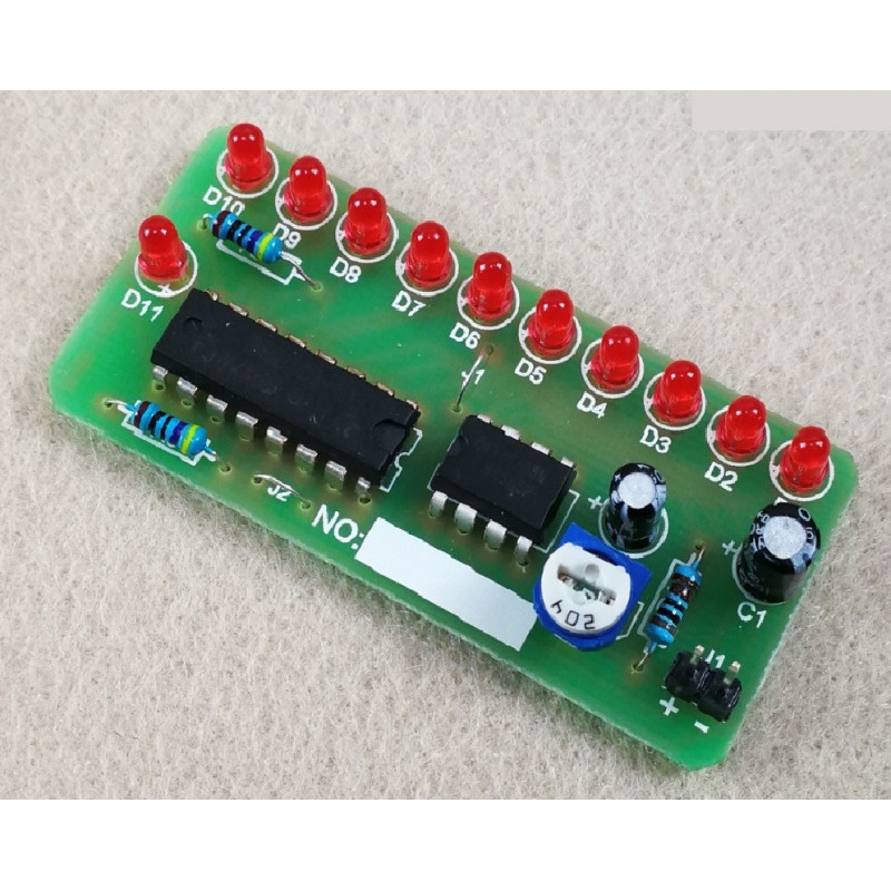
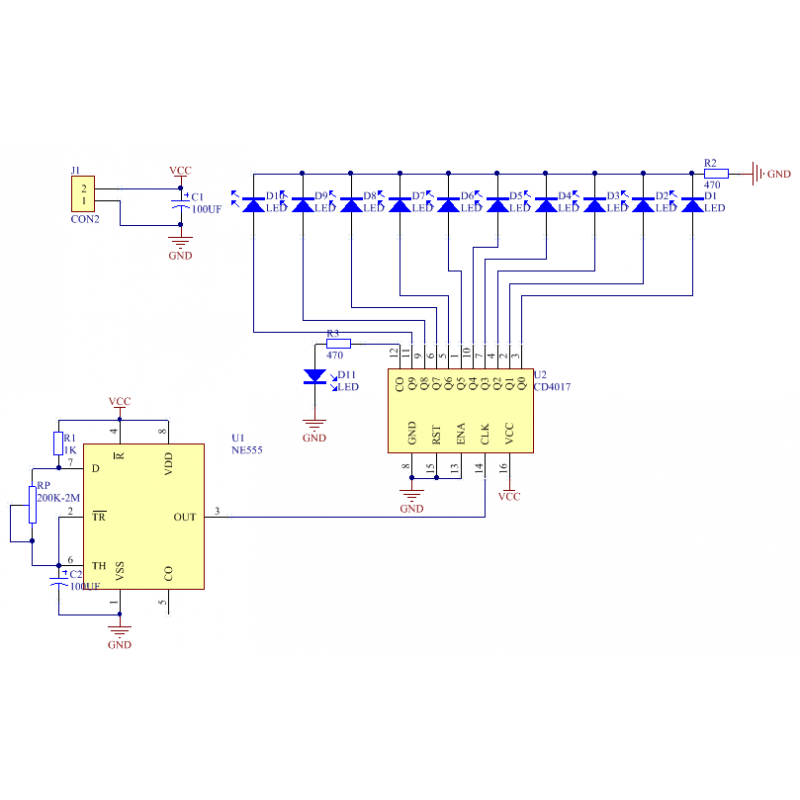
Function introduction: After power is turned on, 10 LEDs will light up in a circular flow, and the speed of the flowing lights can be adjusted. D11 will flash once per cycle. This kit can very intuitively demonstrate the functions of N555 and CD 4017. It is a multi-kit for learning oscillation circuits, counters, frequency dividers, and color light controllers. It has a good effect, is very interesting and practical, and is also the preferred material for beginners. Electronics
Overview:
This kit can intuitively demonstrate the functions of N555 and CD4017.
It is a kit for learning oscillator circuits, counters, frequency dividers, and colored light controllers.
This kit also has good effects, is very interesting and practical, and is the preferred material for beginners.
Circuit function:
10 LEDs light up in a cycle in turn, the speed of the flow can be adjusted, L11 flashes once per cycle, so it is called 10.1 circuit. This circuit fully and intuitively displays the function of 4017, which is very helpful for understanding the circuit and is the best choice for implementing 4017.
Working voltage: 4-12V, the higher the voltage, the brighter the LED will be.
Circuit principle: After power on, NE555 and peripheral circuits form a multivibrator. The oscillation frequency is mainly determined by R1, RP and C2. Adjusting RP can change the oscillation frequency. The oscillation signal of the oscillator is output from pin 3 of NE555 and sent to the counting input terminal (pin 14) of CD4017. Every time a pulse comes, the high level output of Q0-9 of the counter moves 1 bit in turn, lighting up the corresponding light-emitting diode, thus creating a feeling of running water. Among them, L11 is connected to the counting output terminal CO of 4017. When L1-5 is lit, the CO terminal of 4017 outputs a high level and lights up L11. When L6-10 is lit, the CO terminal outputs a low level and L11 is not lit. If you think L11 is unsightly, you can not install it, and it will not affect the circuit operation at all.
Tips:
1. For electrolytic capacitors and LED lights, pay attention to the positive and negative poles.
2. Pay attention to the direction of chip welding, the chip gap corresponds to the direction of the gap marked on the board.
3. The power supply voltage is DC 3V~5V, pay attention to the positive and negative poles.
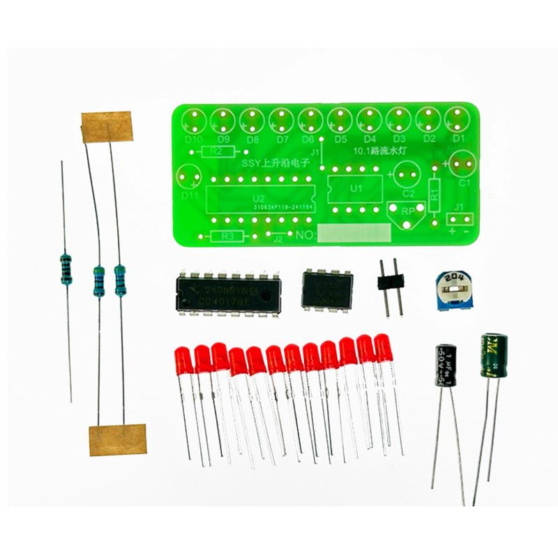
Component List:
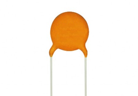
Component Name: Electrolytic Capacitor 100µF
Quantity: 1
Position: C1
Component Name: Electrolytic Capacitor 1µF
Quantity: 1
Position: C2
Component Name: 3MM Red LED
Quantity: 11
Position: D1-D11
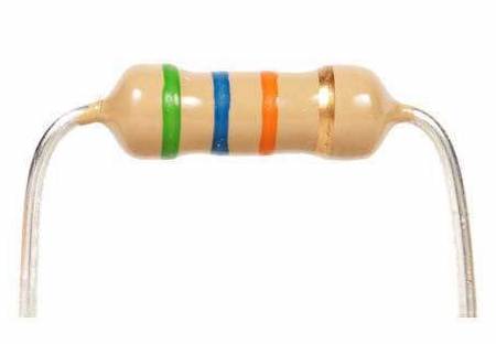
Component Name: 1/4W Resistor 1K
Quantity: 1
Position: R1
Component Name: 1/4W Resistor 470R
Quantity: 2
Position: R2, R3
Component Name: Blue and White Potentiometer 200K
Quantity: 1
Position: RP
Component Name: NE555 DIP Chip
Quantity: 1
Position: U1
Component Name: CD4017 DIP Chip
Quantity: 1
Position: U2
Component Name: 2P Pin Header
Quantity: 1
Position: J1
Component Name: PCB Board
Quantity: 1