How we will approach our orders going forward with the CUPW strike.
Store address and hours
location_on 4131 Fraser St. Vancouver BC Get Directions
phone 604-875-1993 Call us
access_time Hours
| Monday - Friday | 9AM - 5:30PM |
| Saturday - Sunday & Holidays | Closed | See Holiday Hours |

-
 close
close -
CATEGORIES
-
-
-
-
-
-
-
-
-
-
-
-
-
Featured Item
-
-
-
-
-
-
-
more electrical devices
More electrical devices -
more electrical devices
More electrical devices
-
-
more electrical devices
More electrical devices -
more electrical devices
More electrical devices
-
-
Featured Items
-
more electrical devices
More electrical devices
-
-
-
-
-
-
-
-
Featured Item
-
-
-
-
-
-
-
Featured Items
-
-
-
-
-
-
-
-
Featured Items
-
-
-
Featured Items
-
-
-
-
-
-
-
-
-
-
-
Featured Items
-
-
-
-
-
-
-
-
-
Featured Items
-
-
-
-
-
-
featured
-
-
-
Featured Items
-
-
-
-
-
-
-
Featured Items
-
-
-
-
-
Featured Items
-
-
-
-
Featured Products
-
-
-
More Filaments
More Filaments
-
-
-
-
more electrical devices
More electrical devices
-
-
more electrical devices
More electrical devices
-
-
Electrical Devices
-
-
-
more electrical devices
More electrical devices
-
-
-
-
-
-
-
Featured Products
-
-
-
Featured Products
-
-
-
-
BRANDS
-
-
-
-
Brands/Manufacturers
-
-
Manufacturer 3
-
-
- PROJECTS
-
COMMUNITY
-
- SALE Sale
CNC 50mE Laser Engraver Installation and Setup


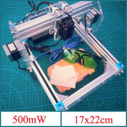
This guide will walk you through the assembly and set up of the CNC 50mW Laser Engraver from Lee's Electronics Components. All parts used in this guide are included in the kit and some replacements parts can be purchased individually. All software used in this guide is freely available online.
This 50mW laser engraver has a working area of about 250mm x 300mm.
Parts:
CNC 50mW Laser Engraver Kit (PID: 15892)
Replacement Parts:
Arduino Nano (PID: 10998)
GT2 timing belt (PID: 15686)
Timing motor pulley (PID: 15790)
JST 2.5mm Jumper Wire (PID: 28595)
Tubing 4mm Spiral Wrap (PID: 10630)
Power Adapter 12V 5A (PID: 16016)
USB mini cable (PID: 21317)
Warning: The 50mW laser included in this kit will damage your eyes if stared directly at. Always wear the included protective eyewear when operating this machine.
Step 1: Assembling the Base Frame


Parts:
2x aluminum extrusions
2x aluminum double extrusions
4x L-shaped brackets
10x set screws
2x securing nuts
2x drive belts
1x control module
Instructions:
1. Assemble the rectangular base with 4 pieces of the aluminum extrusion. Use L-brackets to secure the corners of the frame.
2. Lay the timing belt into the groove of the double-wide extrusion. Leave an equal amount of belt hanging off each end. Secure the belt on one end of the frame using the T-nut and set screw.
3. Attach the control module to the shorter end of the frame.
Step 2: Assemble the Y-axis Stepper Motor


Parts:
2x stepper motors
2x acrylic motor mounting plates
8x ball bearing wheels
8x nylon washers
8x screws
8x nuts
8x screws for motor mounts
Instructions:
1. Attach timing pulley to the stepper motor and then the motor to the largest acrylic plate. The plug on the motor should face upward (refer to image). Attach the timing pulley to the stepper motor and the bearings to the acrylic frame.
2. Use the machine screws and nuts to bolt the bearings and washers to the acrylic plate. Each plate will have 4 bearings attached to it.
2. Repeat the above step so that you will end up with 2 identical servo motor frames.
Step 3: Assembling the X-axis Motor and Laser Mount

Parts:
1x 500mW laser
2x acrylic plates
1x stepper motor
1x pulley wheel
1x drive belt
4x 50mm screws
Instructions:
1. Attach the laser diode to the acrylic sheet using the included screws. Peel away the label on the laser to access the threaded screw holes.
2. Attach the stepper motor to the acrylic sheet. The white JST plug on the servo motor should face upward.
3. Join the 2 acrylic sheets together with the machine screws and nuts. There will be a roller bearing and 2 nylon washers on every screw.
Step 4: Assemble the Stepper Motor Carriage

In this step, we will put together all the individual components that we assembled in the previous steps into one complete machine.
Parts:
1x double aluminum extrusions
1x toothed pulley belt
4x T-nuts
4x hex set-screws
4x 30mm hex screw
2x motor assembly (from step 1)
1x motor assembly (from step 2)
Instructions:
1. Lay the timing belt across the last piece of aluminum extrusion and secure one end of the belt with a T-nut and set screw.
2. Slip the X-axis laser/servo assembly onto the aluminum bar and thread the belt through the pulley. Pull firmly to take the slack out of the belt and then secure the other end to the extrusion with T-nut and set screw.
3. Attach an Y-axis stepper motor to each end of the aluminum extrusion using the included machines screws. The bearings and motor pulleys will face inward.
Step 5: Wiring the Engraver


Parts:
1x spiral wrap
Instructions:
1. Plug the Y-axis JST connector into the 4P port directly adjacent to the barrel jack on the board.
2. Route the left Y-axis stepper motor cable through the center of the X-axis extrusion and plug it into second JST port.
3. Plug the right Y-axis stepper motor cable into the third port from the barrel jack.
4. Plug the laser diode power cable into the 2 port JST plug labeled High Power Laser/fan.
5. Use the spiral loom to wrap the wires to prevent loose wires from snagging while the carriage moves. Ensure there is enough slack in the cable by first moving the carriage to the farthest point from the control board. This should be the top left-hand corner.
6. Attach an acrylic leg to each corner of the base frame. Congratulations! The assembly of the laser engraver is now complete!
Step 6: Download and Install Benbox 3.7.99

Install Benbox Laser Engraver 3.7.99
1. Download and unzip Benbox 3.7.99
2. Select Benbox 3.7.99 and run the setup wizard
3. Download and install the Arduino IDE. https://www.arduino.cc/en/Main/software
4. Click and install CH340 driver.
5. Restart computer
5. Connect the USB cable between computer and engraver.
To install the firmware, click on the lightning symbol at the top of the menu (rightmost icon).
1. Select the appropriate com port.
2. Select nano(328p).
3. Select and install the Lx.Hex firmware.
5. Click install. When the firmware has installed successfully, you will see a green checkmark beside the update firmware title at the top.
Step 8: Setup the Benbox Laser Engraver Parameters

The last step is to set up the parameters for the engraver.
1. Click on the blue menu icon at the top right-hand corner of the software.
2. Click on the right arrow underneath the menu icon to access the parameter list.
3. Enter the parameters' values as depicted in the photo.
Step 9: Making Your First Engraving

Before making your first print, make sure you put on the laser protection glasses that are included in the kit! NEVER LOOK at the laser beam without the protective eyewear. We will focus the laser and align it in this step.
1. Click the circular laser button and adjust until the beam is sharp.
2. Align the laser by clicking the motor control button and move the laser until you have it oriented in the position you want. This starting spot will correlate to the red arc at the (0,0) position (refer to image).
3. Draw an simple image using the drawing tools on the left. To delete any part of your drawing, right click on the part.
4. Press the green start button to start the print. To stop the print at any moment, click on the red stop button.
Congratulation on successfully making your first engraving!
Related product
Related posts
-
 Touch Switch Circuit With Mosfet
10/19/20174441 viewsThe simple touch switch LED circuit utilizes biasing characteristics of the MOSFET.Read more
 -
 Egg Timer
11/16/20182898 viewsThis project demonstrates the basics of digital logic, the characteristics of a NE555 timer, and demonstrates how...Read more
 -
 Arduino Piano Project
10/23/20173032 viewsThis is a piano board with eight push button switches that allows you to play one octave (Do Re Mi Fa So La Si Do)...Read more
 -
 Small AC to DC Converter
03/16/20183291 viewsThe small AC to DC Voltage Converter project uses four diodes to make one bridge rectifier to transfer AC power to DC...Read more
 -
 RF Remote Control Car
03/09/20174103 viewsThe RC car is a great project for all ages and it doesn’t require any programming. It uses simple integrated circuits...Read more


.png)
