



location_on 4131 Fraser St. Vancouver BC Get Directions
phone 604-875-1993 Call us
access_time Hours
| Monday - Friday | 9AM - 5:30PM |
| Saturday - Sunday & Holidays | Closed | See Holiday Hours |


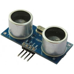
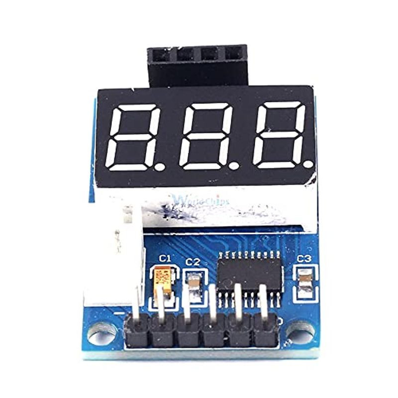
The HC-SR04 Ultrasonic Distance Measurement Control Module automates the use of the HC-SR04 Ultrasonic Range Finder and other ultrasonic modules and provides a direct readout of the distance as well as the measurement in centimeters over a serial port.
This small module includes a built-in microcontroller and 3-digit LED display. Just plug the HC-SR04 Ultrasonic module into the female header and apply 5V and ground. The module will now display the distance in centimeters. The HC-SR04 is good for about 2 to 400cm detection distance which is about 1″ to 13 feet and the display updates the distance every second.
The module also sends the distance data out a serial pin in the format of ‘D:XXX‘ where XXX is the distance in centimeters. The data is sent every second at a baud rate of 9600 and this pin can be monitored by a serial port on an MCU if desired as shown in our example below.
The module has several uses. One is simply to easily test HC-SR04 Ultrasonic modules without having to wire them up to an MCU. Another is to provide a display of the distance data such as when using the HC-SR04 on a robotic vehicle and you want an easy way to monitor the distance that the HC-SR04 thinks it is seeing.
The module has a 4-pin header designed for use with the HC-SR04, but it can be adapted for use with other ultrasonic modules that use the same basic ping interface including the US-100 and HY-SRF05.
HY-SRF05:
To use with the HY-SRF05, you need to remove the resistor R9 on the back of the HY-SRF05 module. This isolates the OUT pin which is not normally used.
Short the OUT pin to the adjacent GND pin.
insert the 5-pin HY-SRF05 header into the 4-pin female header so that the original GND pin is left unconnected. Ground is now supplied through the OUT pin which is now connected to the GND pin.
JSN-SR04T:
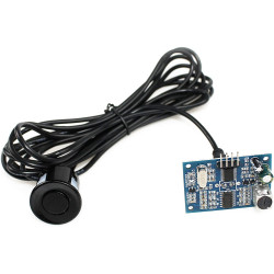
This module is not compatible with the JSN-SR04T waterproof range finder. The JSN-SR04T requires a longer Trigger pulse of approximately 20uS and this module outputs a 14uS Trigger pulse that results in erroneous readings.
There is a 4-pin female header on the assembly for plugging in the HC-SR04 ultrasonic sensor. The sensor is inserted so that it points away from the LED display.
Power and ground can be supplied via the 6-pin male header as shown below or by connecting to the 2-pin JST XH style connector on the board. Observe the polarity markings on the board if using the JST connector.
1 x 6 Male Header
These are pretty handy little modules that work quite well for their designed purpose.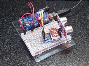
To get up and running only requires connecting power and ground, but the program below shows one method to monitor the serial output of the module so that an MCU can get the distance data and use it for making decisions. In our example, we are just checking for each character and passing it out the USB port so that it can be displayed in the Serial Monitor window to test the device.
In the example, we are using SoftwareSerial.h so that it will work with any Arduino style MCU. If the MCU has an extra hardware serial port, that can be used instead. The RX pin on the module is connected in our example, but it is not actually doing anything as the data is only flowing from the module to the MCU.
Once the program is downloaded, open the Serial Monitor window and ensure that the baud rate is set to 9600. It should be updated with the displayed reading every second which will look something like D:017 where 017 is 17 centimeters.
/*  Simple program to communicate with the HC-SR04 Distance Measurement
     Control Module

  Uses hardware serial to talk to the host computer and software serial for
  communication with the HC-SR04 Distance Measurement Control Module

  Connections
  Arduino 5V to module VCC
  Arduino GND to module GND
  Arduino D9 to module RX
  Arduino D8 to module TX

  When data is received from the HC-SR04 Distance measurement Module, it is
  forwarded to the computer over the USB port where it can be displayed in the
  Serial Monitor window.

  Data uses the format 'D:XXX' where XXX is distance in centimeters

  Uses Softserial.h library
*/
#include <SoftwareSerial.h>
SoftwareSerial SoftSerial(8, 9); // RX | TX pins.  Can be reassigned if needed

const long BAUDRATE = 9600;    // Baud rate of the HC-SR04 control module
char c = ' ';                  // Character from HC-SR04 control module
//===============================================================================
//  Initialization
//===============================================================================
void setup()
{
  SoftSerial.begin(BAUDRATE);  // Init soft serial object
  Serial.begin(9600);          // Init hardware serial
  Serial.println("Test started");
}
//===============================================================================
//  Main
//===============================================================================
void loop()
{
  // Read from the HC-SR04 Control module and send to the Serial Monitor
  if (SoftSerial.available())
  {
    c = SoftSerial.read();
    Serial.write(c);
  }
}
The board has a 4 small holes that can be used for mounting if desired.
| Maximum Ratings | ||
| Vcc | 4.5 – 5.5V (5V typical) | |
| IMax | Maximum Current Draw | 20mA (typical) |
| Operating Ratings | ||
| Measurement Accuracy | Absolute accuracy depends on ultrasonic sensor used | 1% typical |
| Serial Baud Rate | 9600 | |
| Display Units | Centimeters | |
| Dimensions | L x W (PCB) | 55 x 24 mm (1.38 x 0.95″) |
Product ID: 18808

