.png)
All pictures are for illustrative purposes only.
|
Project |
Min |
Typical |
Max |
Unit |
|
Supply Voltage |
4.75 |
5 |
5.5 |
V |
|
Power consumption (@ 5V) |
— |
— |
180 |
mA |
|
Opening and closing times per minute |
— |
— |
30 |
Frequency |
|
Maximum switching voltage per channel |
125VAC/24VDC |
— |
||
|
Maximum switching current per channel |
3 |
A |
||
|
Dimension |
69X54X23 |
mm |
||
|
Net Weight |
43 |
g |
||
NOTE: Place 2 layers of electrical tape on the top of the Arduino's usb connector. This will prevent the relay shield from making contact. Do not operate voltage more than 35V DC.
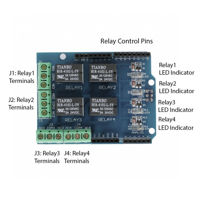
Relay Shield V2.0 terminal connections description
J1 Interface/Terminal Pin Description:
Terminals J2-4 are similar to J1 except that they control RELAY2-RELAY4 respectively.
Note: Only four Arduino Digital I/O pins, pins 4-7, are required to control the four different relays. Additionally the 5V and two GND Arduino pins are also required to power up the Relay Shield.