
location_on 4131 Fraser St. Vancouver BC Get Directions
phone 604-875-1993 Call us
access_time Hours
| Monday - Friday | 9AM - 5:30PM |
| Saturday - Sunday & Holidays | Closed | See Holiday Hours |


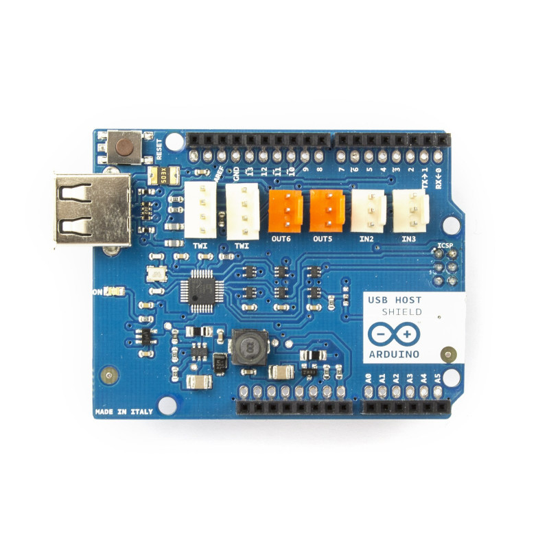
The Arduino USB Host Shield allows you to connect a USB device to your Arduino board. The Arduino USB Host Shield is based on the MAX3421E (datasheet), which is a USB peripheral/host controller containing the digital logic and analog circuitry necessary to implement a full-speed USB peripheral or a full-/low-speed host compliant to USB specification rev 2.0. The shield is TinkerKit compatible, which means you can quickly create projects by plugging TinkerKit modules onto the board.
The following device classes are supported by the shield:
For information on using the shield with the Android OS, see Google's ADK documentation.
Arduino communicates with the MAX3421E using the SPI bus (through the ICSP header). This is on digital pins 10, 11, 12, and 13 on the Uno and pins 10, 50, 51, and 52 on the Mega. On both boards, pin 10 is used to select the MAX3421E.
| Operating Voltage | 5V |
| USB Controller | MAX3421E |
| Max Current | 500mA when Arduino is powered by a suitable power supply connected to the Arduino power jack |
| Max Current | 400mA when Arduino is powered by its USB port |
The Arduino USB Host Shield can be used with the "USB Host Library for Arduino" hosted by Oleg Mazurov and Alexei Glushchenko from circuits@home, Kristian Lauszus and Andrew Kroll on GitHub (download).
Control an RC car using an XBOX wireless game controller;
Here you can find some tutorial developed by circuits@home.
Adding a display to a digital scale using Arduino and USB Host shield;
EAGLE files: USBHostShield-Rev2.zip
Schematic: USBHostShield-Rev2.pdf
The Arduino USB Host Shield has no power jack and is powered only when attached to an Arduino board.
This shield has a MALE USB port where you can attach your USB device.
The shield features several TinkerKit input/output and communication interfaces. Connecting TinkerKit modules can simplify the creation of a project or a prototype. The on-board connectors are :
The maximum length and width of the Motor Shield PCB are 2.7 and 2.1 inches respectively. Four screw holes allow the board to be attached to a surface or case. Note that the distance between digital pins 7 and 8 is 160 mil (0.16"), not an even multiple of the 100 mil spacing of the other pins.
