Store address and hours
location_on 4131 Fraser St. Vancouver BC Get Directions
phone 604-875-1993 Call us
access_time Hours
| Monday - Friday | 9AM - 5:30PM |
| Saturday - Sunday & Holidays | Closed |
| See Holiday Hours | |

-
 close
close -
CATEGORIES
-
-
-
-
-
-
-
-
-
-
-
-
-
Featured Items
-
-
-
-
-
-
-
More mirco-controllers
-
More Developement Tools
-
-
More Prototyping
-
More Modules
-
-
Featured Items
-
More prototyping Tools
-
-
-
-
-
-
-
-
Featured Item
-
-
-
-
-
-
-
Featured Items
-
-
-
-
-
-
-
-
-
-
Featured Items
-
-
-
-
-
-
-
-
-
-
-
Featured Items
-
-
-
-
-
-
-
-
-
Featured Items
-
-
-
-
-
-
Popular Cleaners
-
-
-
Featured Items
-
-
-
-
-
-
-
Featured Items
-
-
-
-
-
Featured Items
-
-
-
-
Featured Products
-
-
-
-
-
more motor
-
-
more power supplies
-
-
Featured Items
-
-
-
more electrical devices
-
-
-
-
-
-
-
Featured Items
-
-
-
-
-
-
BRANDS
-
- PROJECTS
-
COMMUNITY
-
-
-
FEATURED POSTS
-
-
-
- SALE
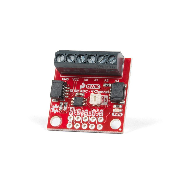
SPARKFUN QWIIC 12 BIT ADC - 4 CHANNEL (ADS1015)
Description
A lot of the time you just need to add more analog inputs to solve a problem. It happens. The SparkFun Qwiic 12 Bit ADC can provide four channels of I2C controlled ADC input to your Qwiic enabled project. These channels can be used as single-ended inputs, or in pairs for differential inputs. What makes this even more powerful is that it has a programmable gain amplifier that lets you "zoom in" on a very small change in analog voltage (but will still effect your input range and resolution). Utilizing our handy Qwiic system, no soldering is required to connect it to the rest of your system. However, we still have broken out 0.1"-spaced pins in case you prefer to use a breadboard.
The ADS1015 uses its own internal voltage reference for measurements, but a ground and 3.3V reference are also available on the pin outs for users. This ADC board includes screw pin terminals on the four channels of input, allowing for solderless connection to voltage sources in your setup. It also has an address jumper that lets you choose one of four unique addresses (0x48, 0x49, 0x4A, 0x4B). With this, you can connect up to four of these on the same I2C bus and have sixteen channels of ADC. The maximum resolution of the converter is 12-bits in differential mode and 11-bits for single-ended inputs. Step sizes range from 125μV per count to 3mV per count depending on the full-scale range (FSR) setting.
We have included an onboard 10K trimpot connected to channel A3. This is handy for initial setup testing and can be used as a simple variable input to your project. But don't worry, we added an isolation jumper so you can use channel A3 however you'd like.
NOTE: The I2C address of the ADS1015 is 0x48 and is jumper selectable to 0x49, 0x4A, 0x4B. A multiplexer/Mux is required to communicate to multiple ADS1015 sensors on a single bus. If you need to use more than one ADS1015 sensor consider using the Qwiic Mux Breakout.
- ADS1015
- Operating Voltage (VDD): 2.0V-5.5V
- (Note: When powering with a Qwiic cable, the input range is only 3.3v)
- Operating Temperature: -40°C to 125°C
- Operation Modes: Single-Shot, Continuous-Conversion (Default), and Duty Cycling
- Analog Inputs:
- Measurement Type: Single-Ended (Default)
- Input Voltage Range: GND to VDD
- Full Scale Range (FSR): ±.256V to ±6.114V (Default: 2.048V)
- Resolution:
- 12-bit (Differential) or 11-bit (Single-Ended)
- LSB size: 0.125mV - 3mV (Default: 1 mV)
- Sample Rate: 128 Hz to 3.3 kHz (Default: 1600SPS)
- Current Consumption (Typical): 150μA-200μA
- I2C Address: 0x48 (Default), 0x49, 0x4A, or 0x4B
- Operating Voltage (VDD): 2.0V-5.5V
- Screw pin terminals for solderless connection to voltage sources
- Four unique I2C addresses:
- 0x48
- 0x49
- 0x4A
- 0x4B
- 2x Qwiic connection ports
- Onboard 10K trimpot
Frequently bought together
Related products


.png)
