.png)


All pictures are for illustrative purposes only.
The assembly steps:
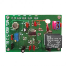
Step 1: Welding circuit
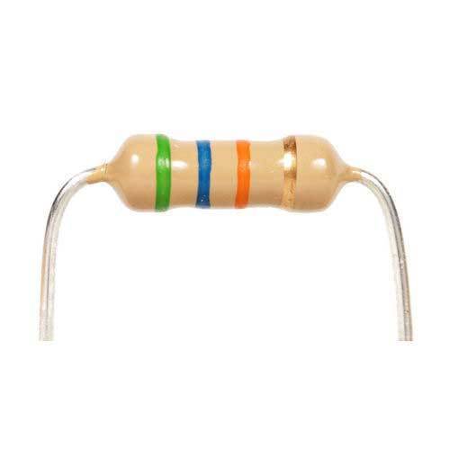
Electric welding part is simpler, welding sequence according to the principle of component level from low to high, the first welding eight resistance, is important to use multimeter to confirm resistance is correct, D4, D5 R13 R14 can temporarily not welding, integrated circuit chips can temporarily not inserted
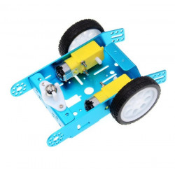
Step 2: Mechanical assembly
The red line is connected to the 3V positive power supply, the yellow line grounding, excess wire can be used for motor wire.
Step 3: The installation of a photoelectric circuit
Photosensitive resistance and light-emitting diodes (note polarity) is reverse-mounted on the PCB, and the ground distance is about 5 mm, both photosensitive resistance and light-emitting diodes are 5 mm distance. Finally, you can power test.
Step 4: Vehicle debugging
The right direction is along the universal wheel direction, if you press and hold the left photoresistor, the wheels on the right side of the car should be rotated. Press and hold the right photoresistor, the wheels on the left side of the car should be rotated, if the car driving back, can also exchange the wiring of two motors, if the one side normal and the other side back up, as long as you can swap wiring of back side.
For details, please visit the manual
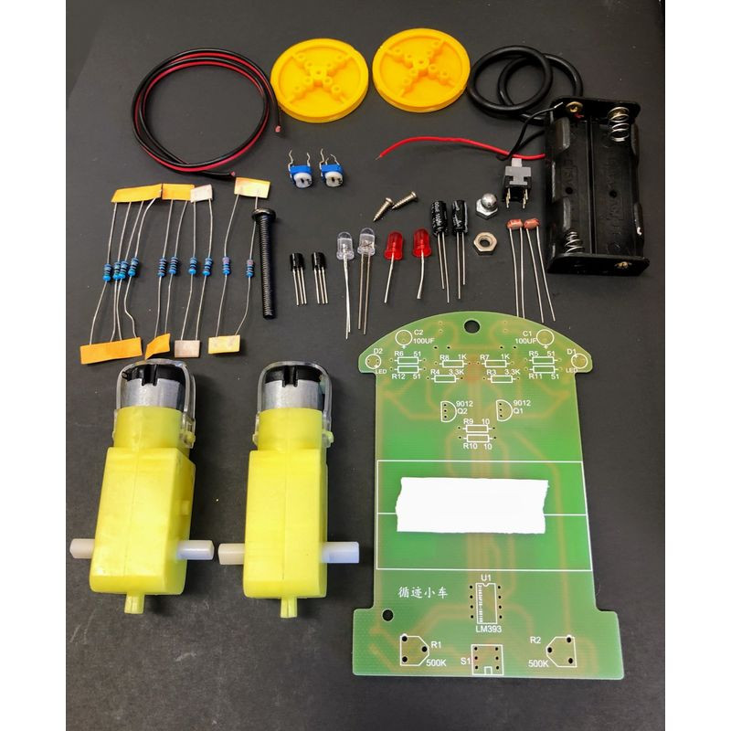
Packing List
1 * LM393 IC
1 * IC socket
1 * Pack of screws
10 * Resistors
2 * 10K Adjustable resistors
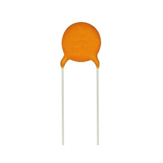
2 * Capacitors
1 * Switch
2 * S8050 NPNs
2 * Photo resistances
2 * White LEDs
2 * Red LED
1 * PCB
1 * Battery box (batteries are not included)
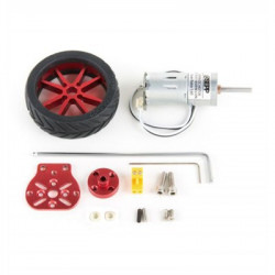
2 * Car tires
2 * Gear motors
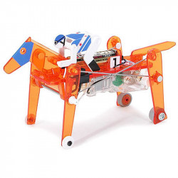
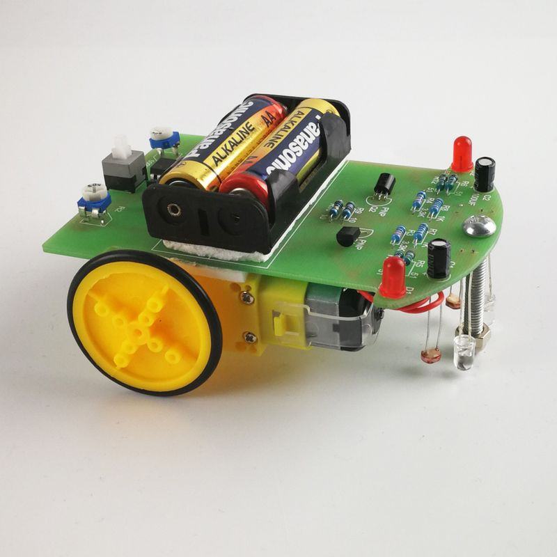
After successfully assembling the kit, the car can move forward along the black track with a width of about 15mm. The circuit consists of photoelectric sensor, voltage comparison, and motor drive. The reflectivity of the light-emitting tube projected to the black and white parts is different, and the resistance value of the received photoresistor will change. LM 393 compares the size of the two photoresistors and controls the operation of the motors on both sides, thereby correcting the direction of the car to ensure that the car moves along the black track. The motor is equipped with a deceleration device. Please do not rotate it vigorously by hand to prevent damage.
Circuit board size: 10cm x 7cm
Note: Batteries not included.