.png)


All pictures are for illustrative purposes only.
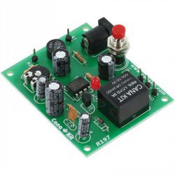
Circuit Introduction
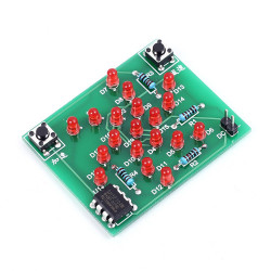
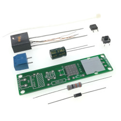
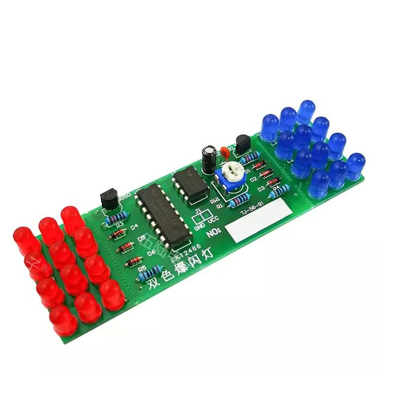
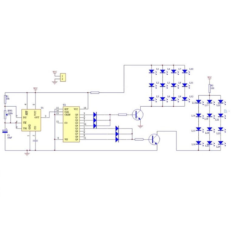
This kit uses NE555 and CD4017 chips to form a simulated warning light circuit. The blue LED and red LED flash alternately according to the pulse. The flashing frequency can be adjusted by adjusting RP1. The circuit working voltage is DC9-12V, and the kit does not include a power supply (battery). The kit is simple to make, has obvious effects, and is very interesting. It is suitable for electronic enthusiasts and vocational school students to practice assembly.
Circuit board features
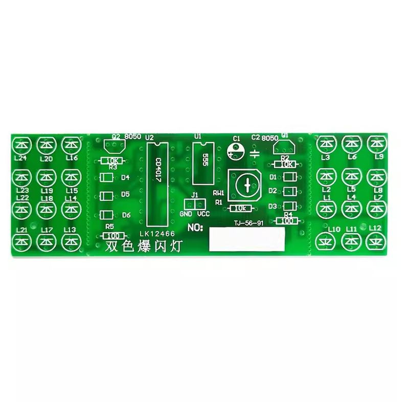
It is made of 1.5mm high-quality bakelite and has a beautiful layout of components. It is specially optimized for practical training and has a high cost-effectiveness. The red flashing light and the blue flashing light are made into separate boards and connected to the main board through the stamp hole. Generally, they do not need to be removed and will work immediately after installation. If you need to install it separately to other places or increase the distance, you can remove it from the stamp hole and connect it to the main board through two wires, so that it can be installed anywhere else. The kit provides detailed information such as schematics, and there are numbered locations on the board for convenient practical training and identification.
Working Principle
This kit consists of a multivibrator composed of NE555 and a CD4017 decade counter/pulse distributor. When the 3rd, 5th pulses arrive, Q0, Q2, and Q4 output high levels in turn, and the blue LED flashes 3 times. When the 6th, 8th, and 10th pulses arrive, Q5, Q7, and Q9 output high levels in turn, and the red LED flashes 3 times. When the 1st, 13th, and 15th pulses arrive, the blue LED flashes again, and the blue and red LEDs flash alternately in a cycle, forming a simulated warning light. Changing the size of RP1 can change the oscillation period, thereby changing the speed of the LED flashing. The entire circuit can work with DC9-12V.
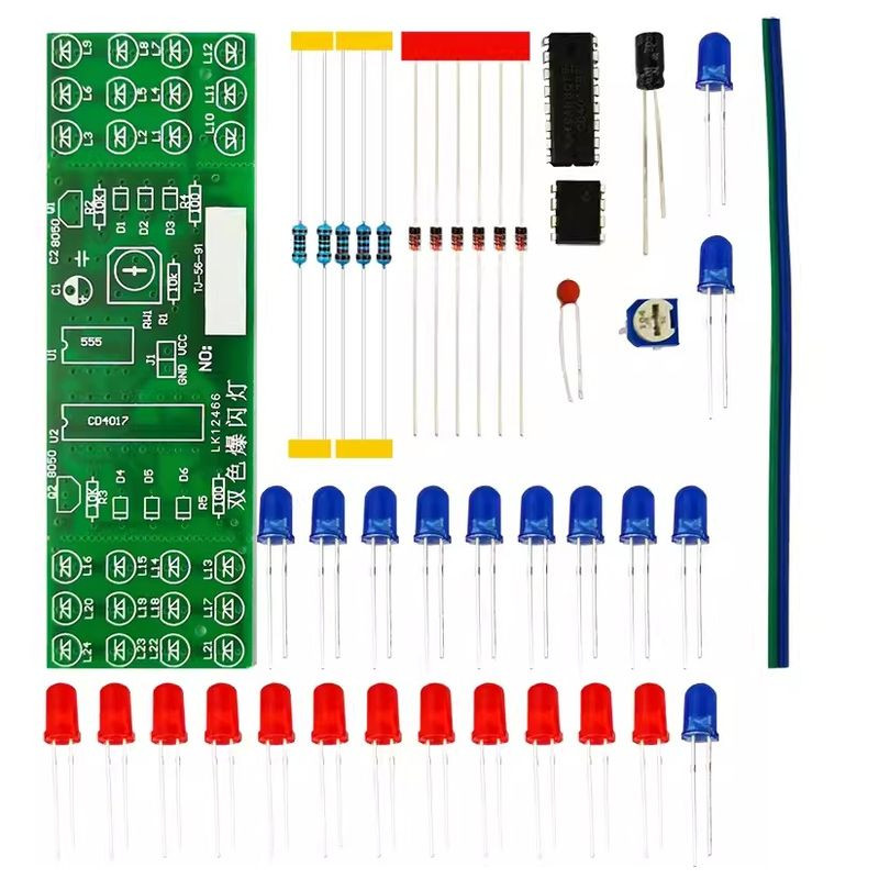
Packing List
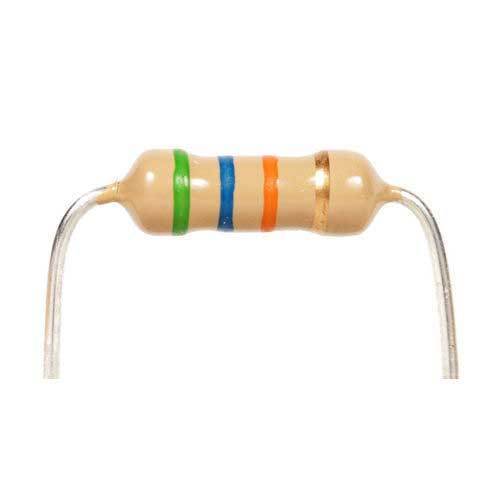
10k Resistor R1,R2,R3 x3
100 ohm Resistor R4, R5 x2
100k Potentiometer RW1 x1
1N4148 D1-D6 x6
Blue LED L1-L12 x12
10uf Electrolytic Capacitor C1
Red LED L13-L24 x12
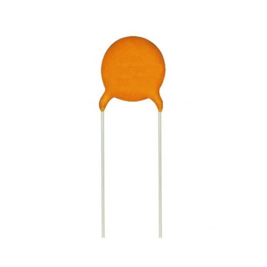
Ceramic Capacitor 103 C2 x1
Transistor 8050 Q1,Q2 x2
IC CD4017 U2 x1
16 pin IC socket U2 x1
NE555 U1 x1
8 pin IC socket U1 x1
10cm Red Wire x1
10cm Black Wire x1
PCB x1