.png)
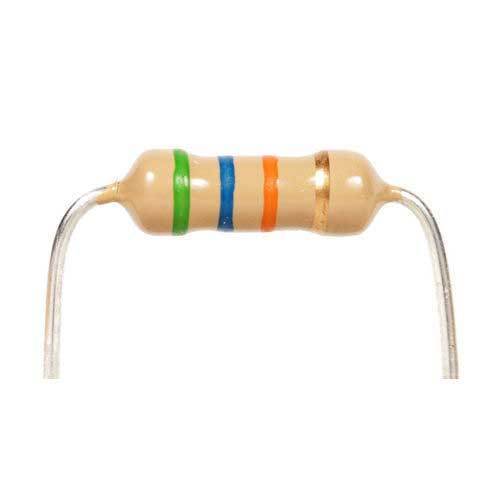
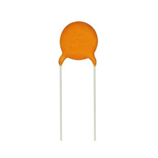


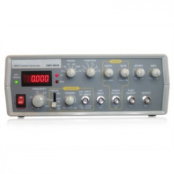
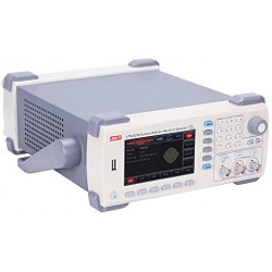
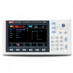
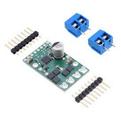
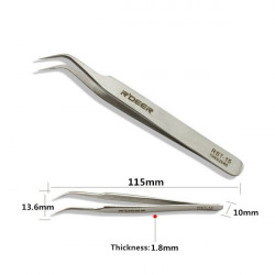
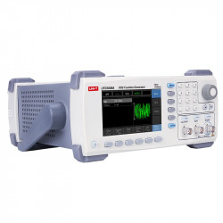
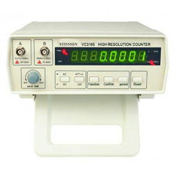
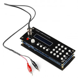
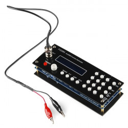
All pictures are for illustrative purposes only.
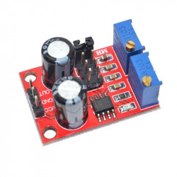
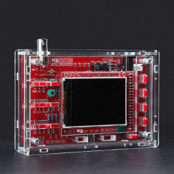
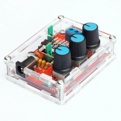
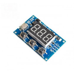
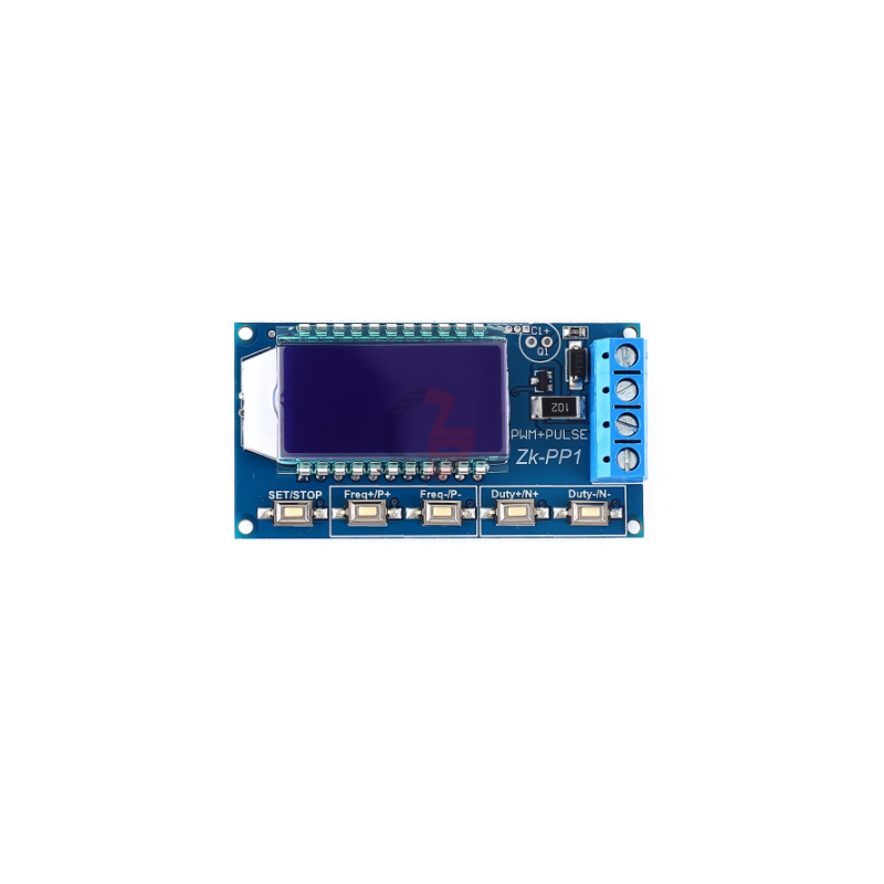
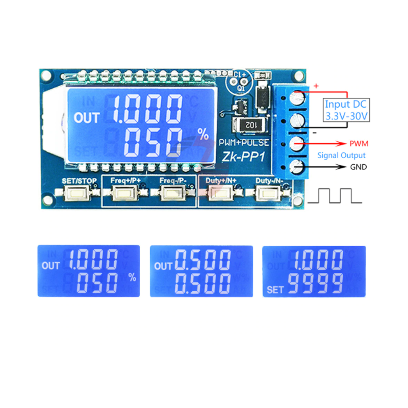
PWM output, you can set the frequency, duty cycle;
Frequency is divided into four ranges, automatic switching:
XXX (no decimal point): the smallest unit is 1Hz, the value range of 1Hz ~ 999Hz;
X.XX (decimal point in the hundred) the smallest unit is 0.01Khz, the range of 1.00Khz ~ 9.99Khz;
XX.X (decimal point in ten): the smallest unit is 0.1Khz; value range of 10.0KHz ~ 99.9KHz
X.X.X (decimal point in ten and hundred): the smallest unit is 1Khz; value range 1KHz ~ 150KHz
e.g. frequency display:
100 indicates PWM output 100Hz pulse; 1.01 indicates PWM output 1.01K pulse; 54.1 indicates that the PWM output has a pulse of 54.1 kHz; 1.2.4 indicates that the PWM output is 124 kHz pulse;
Duty cycle range: 0 ~ 100%;
All set parameters, power-down automatically saved.
LCD display frequency and duty cycle, very clear, PWM output can be set to the frequency and duty cycle;
Wide frequency range, high precision;
Serial communication, TTL level
The module has four independent keys, used to set the frequency and duty cycle, support touch (increase or decrease a unit) and long press (fast increase or decrease), set the parameters automatically save, power down Not lost.
Used as a square wave signal generator, generate square wave signal for experimental development and use;
Used to generate a square wave signal that controls the motor driver;
1. set the frequency of the PWM
2. set the PWM duty cycle
3. read the set parameters