All pictures are for illustrative purposes only.
Happy Holidays! Our store will be closed December 25th, 26th and January 1st for Christmas and New Years.
Store address and hours
location_on 4131 Fraser St. Vancouver BC Get Directions
phone 604-875-1993 Call us
access_time Hours
Monday - Friday | 9AM - 5:30PM |
Saturday - Sunday & Holidays | Closed | See Holiday Hours |

Open • Closes at 5:30PM
close
Menu
-
close
-
CATEGORIES
-
-
-
-
-
-
-
-
-
-
-
-
-
Featured Items
-
-
-
-
-
-
-
More mirco-controllers
-
More Developement Tools
-
-
More Prototyping
-
More Modules
-
-
Featured Items
-
More prototyping Tools
-
-
-
-
-
-
-
-
Featured Item
-
-
-
-
-
-
-
Featured Items
-
-
-
-
-
-
-
-
Featured Items
-
-
-
-
-
-
-
-
-
-
-
-
-
Featured Items
-
-
-
-
-
-
-
-
-
Featured Items
-
-
-
-
-
-
Popular Cleaners
-
-
-
Featured Items
-
-
-
-
-
-
-
Featured Items
-
-
-
-
-
Featured Items
-
-
-
-
Featured Products
-
-
-
-
-
more motor
-
-
more power supplies
-
-
Featured Items
-
-
-
more electrical devices
-
-
-
-
-
-
-
Featured Items
-
-
-
-
-
-
BRANDS
-
- PROJECTS
-
COMMUNITY
-
-
-
FEATURED POSTS
-
-
-
- SALE
- GST/HST Break
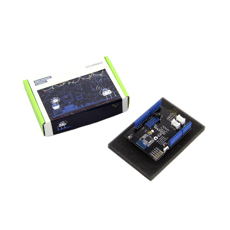
ARDUINO BLUETOOTH BLE SHIELD
Description
BLE Shield stands for Bluetooth Low Energy (BLE) Shield. It is designed to work with Arduino boards or compatibles, including Arduino Uno, Mega 2560, Leonardo and Due. It allows you to connect your Arduino boards with other BLE Central device like a smartphone or tablet. So you can develop some applications like:
•Control your Arduino pins with our/your own mobile App
•Send sensor data from your Arduino to an App for processing
•Use your mobile device as an internet gateway for your Arduino
•and much more!
BLE shield could operate under 3.3V or 5V, therefore it works with a lot of Arduino compatible boards too.
This Seeed BLE Shield utilizes an HM-11 module to provide your Arduino/Seeeduino with serial BLE function. It only takes two pins of the micro controller to communicate your device with this shield. With support for a BLE ComAssistant APK, this BLE Shield can talk to your mobile phone more easily without pairing. You can use it in many conditions, like robot controls or remote control equipment ,etc. We prepared an easy and convenient command set for this shield so that you can use neat and concise code to run the function.
New Features in BLE Shield Version 2.1
1.Reset button is changed to "side button"
2.nRF8001 SPI pins can be set to either Pins 11-13 on the side or ICSP, this allows other Arduino compatible boards with no ICSP header such as FRDM-KL05 board, RedBoard and so on to interface with the nRF8001 BLE chip
3.Flexible REQN and RDYN pins selectable from pin 2 to 10
4.The board is shorter than before and this allows it to fit on Arduino Yun physically
Features Since v2.0
1.Besides the on-board PCB antenna, option to use SMA connector for external antenna (soldering is required)
2.Flexible REQN and RDYN pins selectable from pin 2 to 12, these pins are fixed at 8 & 9 for BLE Shield v1
3.Reset button also resets the Arduino board, and vice versa
4.ICSP header provides Vcc (for other shields to get power source)
5.ICSP header now passes through (for other shields to connect to the SPI)
6.Shield's reset is controllable by Arduino pin 4 or 7
7.Reset signal to the shield is now active low (i.e. pull low to reset the shield)
8.Added test points for power consumption measurement of the nRF8001 chip (soldering is required)
9.Added circuitry and test pin (J9 NC) for measurement of instant working current (using logic analyzer, 1mA = 100mV).
Supported BLE Central Devices
iOS 7
•iPhone 4s
•iPhone 5 (all models)
•iPod touch 5
•iPad 3/4/mini/Air
Android 4.3 or above (4.4 recommended for stability) with Bluetooth 4.0 hardware support
•Nexus 4
•Nexus 7
•Samsung Note 3 / GT-I9300 / GT-I9500
(please report any other Android devices supported)
Windows 8.1 with built-in Bluetooth 4.0 or USB dongle
Mac OSX 10.9.2 with built-in Bluetooth 4.0 or USB dongle
Linux with BlueZ 5.1 with built-in Bluetooth 4.0 or USB dongle
Getting Started Guide
We have prepared a step-by-step guide Getting Started with BLE Shield to show you how to connect your BLE Shield with our free iOS and Android Apps.
How It Works
•BLE Shield communicates with Arduino through the ACI (Application Controller Interface). The ACI is similar to SPI but does not actually work as SPI. SPI is consist of MOSI, MISO, SCK and SS, whereas ACI is consist of MOSI, MISO, SCK, REQN and RDYN.
•Since BLE Shield may receive data anytime even not selected by SPI master (Arduino), so the SS line is not needed.
•In ACI,data exchanged still through MOSI and MISO, and SCK provides the clock generated by master.
•When master wants to request data from BLE Shield, it puts the REQN to low until RDYN line is put to low by BLE Shiled, and then master generates the clock to read out the data. After reading out the data, master will release the REQN and BLE Shield release the RDYN, put them to high.
•If BLE Shield has data to transmit to master, it will put the RDYN to low to indicate master, even though master havn't requested data and REQN is idle. If master detectes a low level condition on RDYN, it will put REQN to low and generate the clock to read out the data.After reading out the data, both REQN and RDYN will be put to high.Note that REQN is controlled by master while RDYN is controlled by BLE Shield.
Technical Details
Nordic nRF8001 Bluetooth Low Energy IC
•Support Peripheral (Slave) role operation only – nRF8001 IC limitation.
•Proprietary simple serial interface – Application Controller Interface (ACI).
•Please refer to Nordic’s nRF8001 Product Specification for more details.
Application Controller Interface (ACI)
•The ACI enables an application controller to communicate with nRF8001.
•The physical ACI interface on nRF8001 consists of five pins. All ACI data and exchanges use a standard SPI interface, with nRF8001 using a mode 0 slave interface to the application controller.
•However, nRF8001 does not behave as a pure SPI slave device; nRF8001 can receive new data over-the-air at any time or be busy processing a connection event or new data. Consequently, the traditional CSN signal used to initiate an SPI transaction is replaced by two active low hand-shake signal; RDYN and REQN.
Signal | Arduino | nRF8001 | Description |
MISO | Input | Output | SPI: Master In Slave Out |
MOSI | Output | Input | SPI: Master Out Slave In |
SCK | Output | Input | SPI: Serial data Clock |
REQN | Output | Input | Application controller to nRF8001 handshake signal |
RDYN | Input | Output | nRF8001 to application controller handshake signal |
Shield Layout
A. nRF8001 & Arduino board Reset Button
B. Factory Testing Pins
C. Power On LED
D. Flexible REQN and RDYN pins from pin 2 to 10
E. External Antenna
F. Onboard Antenna
G. Nordic nRF8001
H. Optional Pin to Control the Shield’s reset
I. Power Consumption Measurement of the nRF8001 chip
J. Power Monitor on Oscilloscope
K. SPI interface connection for nRF8001
Resources
Please visit our wiki page for more info about this product. It will be appreciated if you can help us improve the documents, add more demo code or tutorials. For technical support, please post your questions to our forum.