


.png)


RF Remote Control Car

Created By: Kevin Shu
Overview
The RC car is a great project for all ages and it doesn’t require any programming. It uses simple integrated circuits (IC) and it is controlled wirelessly by a remote controller. The remote controller sends out a encoded radio-frequency (RF) signal to the RC car. The RC car decodes the signal and moves accordingly. The car moves like a tank: to turn left, the right motor is turned on and pivots on the left wheel, and vice versa.
Parts and Tools
Electronic
- 1x Voltage Regulator 7805 (Lee’s ID: 7115)
- 1x 1N4001 Diode (Lee’s ID: 796)
- 1x Heat Sink, TO-220 (Lee’s ID: 10462)
- 1x HT12E Encoder (Lee's ID: 16295)
- 1x HT12D Decoder (Lee's ID: 16296)
- 1x RF Link Transmitter 434MHz (Lee’s ID: 11089)
- 1x RF Link Receiver 434MHz (Lee’s ID: 11090)
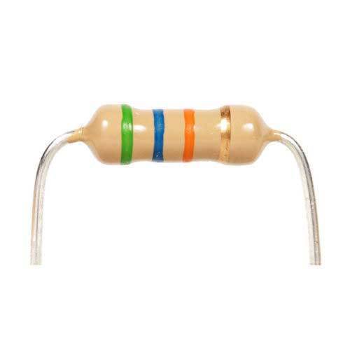
- 1x 1/4W 1K Resistor (Lee's ID: 91901)
- 1x 1/4W 3.3K Resistor (Lee’s ID: 91452)
- 1x 1/4W 47K Resistor (Lee’s ID: 91523)
- 1x 1/4W 1MEG Resistor (Lee’s ID: 94730)
- 1x L293D Half-Bridge Driver (Lee’s ID: 71198)
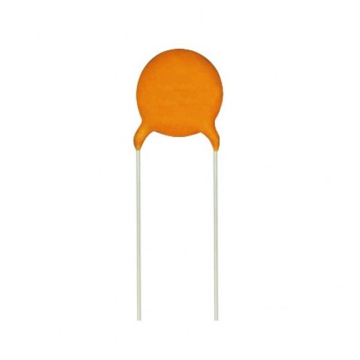
- 2x Electrolytic Cap 16V 100uF (Lee’s ID: 872)
- 2x 5mm Green LED (Lee’s ID: 550)
- 2x DPDT Rocker switch (Lee’s ID: 32842)
- 1x 9V Battery Clip (Lee’s ID: 6538)
- 1x 9V Battery (Lee’s ID: 83741)
- 1x Plastic Enclosure (Lee’s ID: 10361)
- 1x Robot 3-wheel Chassis kit (Lee’s ID: 100259)
- 1x SPST Rocker Switch (Lee’s ID: 31061)
- 1x Hook Up Wires AWG22 Solid (Lee’s ID: 22491)
- 4x Insulated Quick Connector Red Female (Lee’s ID: 6023)
- 4x Quick Connector Red Male (Lee’s ID: 6216)
Tools
- 1x Wire Stripper (Lee’s ID: 103252)
- 1x Nose Plier (Lee’s ID: 10310)
- 1x Diagonal Cutter (Lee’s ID: 10383)
- 1x Soldering Station (Lee’s ID: 11000)
- 1x Solder (Lee’s ID: 10691)
- 1x Desoldering Pump (Lee’s ID: 10103)
- 1x Box Cutter or Utility Knife
- 1x Lighter
Step 1: Building the Chassis


To build the chassis, we will use the chassis kit. The kit includes the following items:
-
1x Plastic base chassis
-
1x 4-AA cell battery holder
-
2x DC gear motor 3-6V
- 2x Rubber tires (65mm Diameter)
-
1x Caster wheel
-
2x 20-line encoder wheels for rpm/speed measurement • 1x SPST rocker switch
-
4x Plastic fasteners
-
4x M3x30 screws
-
8x M3x6 screws
-
8x M3 nuts
-
4x M3x12 spacers
-
1x Installation sheet
Using the kit, we will assemble the chassis.
-
Tear off the yellow protection wrap of the chassis and fasteners.
-
Insert the fastener into the four slits and the rocker switch according to the picture above.
-
Attach the encoder wheel to the side of the motor. The encoder wheels face toward the inside of the car.
-
Mount the two motors to the fastener using the M3x30 screws and M3 nuts. Make sure that the yellow end of the motor is facing the front.
-
Mount the battery holder on the other side of the motor using the M3x6 screws and M3 nuts. This will be the top side of the car.
-
Mount the caster wheel on the bottom side of the car using the M3x12 spacers and M3x6 screws.
Step 2: Building the Receiver


Printed Circuit Board: Parts ID Table
- U1: HT12D decoder (Lee's ID: 16296)
- U2: L293D half-bridge driver (Lee’s ID: 71198)
- U3: RF link receiver (Lee’s ID: 11090)
- D1: 1N4001 diode (Lee's ID: 796)
- R1: 50k resistor (Running 47k and 3.3k resistor in series to get 50k)
- R2: 1K resistor (Lee's ID: 91901)
- LED1: 5mm green LED (Lee's ID: 550)
- S1: SPST rocker switch (Lee's ID: 31061)
Assembling the Printed Circuit Board
- Insert the components (U1, U2, U3, D1, R1, R2, and 4-AA cell battery holder) into their destination according to their parts ID as listed above.
- Solder each component and desolder if necessary. Make sure the polarity of the diodes, LED, battery holder, and the orientation of the IC chips are in the correct position. A common polarity marker is a half-moon shape at one end of the chip. Another is a small dot by pin 1, or sometimes a small triangle or tab instead. From that polarity mark, move counterclockwise around the chip, and number the pins starting at 1 as illustrated below.
- Trim the excess leads of the components with the diagonal cutter.
- Insert the SPST switch into the enclosure.
- Wire and solder the SPST switch to S1 on the printed circuit board accordingly. Leave approx 3 cm length of wire. This will provide ON/OFF to the board.
- Insert the 5mm green LED into the enclosure.
- Wire and solder the 5mm green LED to LED1 on the printed circuit board accordingly. Leave approx 3 cm length of wire. The LED will light up when the signal from the transmitter to the receiver is received.
- With a 8 cm long wire as the antenna, solder it to the ANT on the printed circuit board. Curl it up into a spiral with a pen.
Attachments

Step 3: Building the Enclosure for the Transmitter


- Use the cutout template and cut the two DPDT rocker switches and SPST switch. Note: The cutouts are a 1 to 1 ratio so when printing, make sure to not stretch the picture in any way.
- Align the outlines on the plastic enclosure.
- Using a lighter, heat the tip of the utility knife’s blade. Caution: Children should ask their parents for help before doing the next step.
- While in a well-ventilated room, cut out the switches with the knife while keeping the blade hot. Reheat as necessary. Caution: Do not inhale the black smoke from the burned plastic.
- Fit the switches into the enclosure and make the necessary adjustments. Use 5mm drill bit and drill a hole for the 5mm green LED.
- Use a 2mm drill bit and drill a hole for the antenna.
- The finished product should look like something above.
Step 4: Building the Transmitter


Printed Circuit Board: Parts ID Table
- U1: 7805 voltage regulator (Lee’s ID: 7115)
- U2: HT12E encoder (Lee's ID: 16295)
- U3: RF link transmitter (Lee’s ID: 11089)
- R1: 1M resistor (Lee's ID: 94730)
- R2: 1K resistor (Lee's ID: 91901)
- C1 & C2: 16V 100uF electrolytic capacitor (Lee’s ID: 872)
- LED1: 5mm green LED (Lee’s ID: 550)
- S1: SPST rocker switch (Lee’s ID: 31061)
- S2: DPDT rocker switch (left) (Lee’s ID: 32842)
- S3: DPDT rocker switch (right) (Lee’s ID: 32842)
Assembling the Printed Circuit Board
- Insert the components (U1, U2, U3, C1, C2, R1, R2, and 9V battery clip) into their destination according to their parts ID as listed above.
- Solder each component and desolder if necessary. Make sure the polarity of the capacitors, battery clip, and the orientation of the IC chips are in the correct position.
- Trim the excess leads of the components with the diagonal cutter.
- Wire and solder each of the DPDT rocker switch, left rocker switch and right rocker switch, accordingly to the picture above. Pin 1 and 6 is connected together. Pin 2 and 5 is connected together.
- Insert the DPDT rocker switches into the enclosure.
- Solder the VCC and GND of the left & right DPDT rocker switch to the S2 and S3 on the printed circuit board accordingly. Leave approx 3 cm length of wire.
- Using a piece of wire (approx 3 cm long), solder one end to one of the pins of the HT12E (10, 11, 12, 13). Crimp the other end with a male quick connector. Repeat for the other pins.
- Using another 3 cm long wire, solder one end to one of the DPDT rocker switch pins (3, 4). Crimp the other end with an insulated female quick connector. Repeat for the other pins and rocker switch.
- Connect the male and female quick connectors together accordingly to the table below.
- Insert the SPST switch into the enclosure.
- Wire and solder the SPST switch to S1 on the printed circuit board accordingly. Leave approx 3 cm length of wire. This will provide ON/OFF to the board.
- Insert the 5mm green LED into the enclosure.
- Wire and solder the 5mm green LED to LED1 on the printed circuit board accordingly. Leave approx 3 cm length of wire. The LED will light up when the board is switched ON.
- With a 8 cm long wire as the antenna, solder it to the ANT on the printed circuit board. Curl it up into a spiral with a pen.
Attachments
Step 5: Circuit Diagrams


Above are pictures of the circuit diagram of both the transmitter and receiver.
Step 6: Troubleshooting
Everyone makes mistakes and it is important to stay calm and debug your circuit/wiring.
Soldering
- Tin the tip of the soldering iron with a small amount of solder. Wipe it clean on a damp sponge and then add a small amount of solder again - this helps the heat to flow onto the joint quickly.
- Ensure that all surfaces to be soldered are clean and free from grease.
- Heat the lead of the component and the pad with the tip of the soldering iron.
- Slowly and apply the solder into the joint and let the solder flow into the pad. The ideal shape of a good solder joint should look like a volcano.
- Remove the soldering iron after applying some solder. If the iron is left on the pad for too long, the pad may fall off the circuit board. The flux in solder will burn off causing the solder to oxidize. So always let the solder to cool a little before adding more, typically a couple of seconds is enough.
- Once the solder joint is in the ideal shape, let it cool and solidify.
- Trim the excess lead with diagonal cutters.
- To test a solder joint, use the continuity function on the multimeter. Touch the leads together and make sure the multimeter beeps.
- Touch the leads on two points of the opposite sides of your solder joint. The multimeter will beep if there is continuity detected.
Power Supply
- Make sure that the red lead of the battery clip/holder is connected to the positive pad of the circuit board and the black lead is connected to the negative pad.
- Use the continuity function on the multimeter and check the positive and negative pads. If it beeps then there is short in the circuit which may have also damaged the components.
- You should never connect the battery until you perform the continuity test.
LED
Make sure that the polarity of the LED is correct. The longer lead is the positive end and the shorter is the negative. Also, the pin on the flat side of the LED is the negative.
Diode and Electrolytic Capacitor
Make sure that the polarity of the diode and capacitor is correct. The diode/capacitor will have a line marked on itself. This indicates the negative side.
Wiring
- Trace the circuit, making sure that each component is wired correctly.
- All the VCC should be connected together. All the GND are connected together.
- Use a multimeter and measure the voltage of the pins. All pins connected to VCC should be voltage of the battery and GND should be 0.
- Have someone else to check your circuit, you may not see it but they may.