.png)


All pictures are for illustrative purposes only.
Product Details - [Parameters]
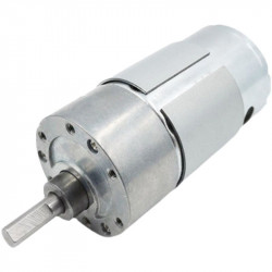
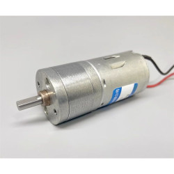
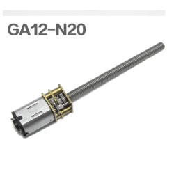
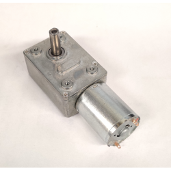
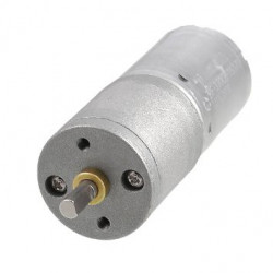
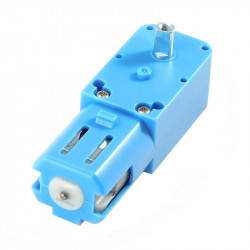
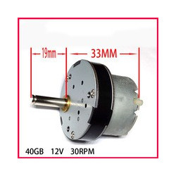
Motor name: 3-wire Hall speed measurement TT motor
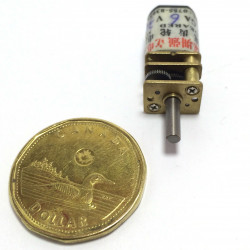
Motor material: metal shaft
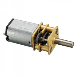
Reduction ratio: 1:48
Torque 1.2N.m
Drive voltage: 5V-12V (6-9V recommended)
Drive current: rated 0.25A
Stall current: 0.6A
Speed comparison: motor 7000±5% rpm wheel axle 155±5%rpm
Encoder type: incremental Hall AB phase encoder
Encoder line number: 3-wire
Interface type: PH2.0 6P
Special function: comes with pull-up shaping, the microcontroller can read directly
Tips with measuring with oscilloscope:
If two signals have a 90-degree phase difference, they are orthogonal. Two signals with a 90-degree phase difference allow for determining the motor's rotation direction based on which signal leads.
The distance traveled by a tire can be calculated based on the number of signal pulses per unit time and the tire's circumference. Detecting only the A/B phase pulses per unit time can also measure the motor's speed.
Taking a three-wire encoder TT geared motor as an example: the motor outputs 3 pulses per single phase per rotation. With a 1:48 reduction ratio, the motor output shaft's one revolution can produce a maximum of 576 pulses (reduction ratio * number of pulses * frequency multiplication, i.e., 48 * 3 * 4 = 576 pulses). The A and B phases output pulse signals with a 90° phase difference, which allows for detecting the motor's rotation direction.
Pinout:
① Encoder ground (GND)
② Encoder output A phase (A)
③ Encoder output B phase (B)
④ Encoder positive pole (VCC)
⑤ Motor line + (M+)
⑥ Motor line - (M-)
Wiring tips: M+ and M- are connected to the motor driver output, A and B are connected to the microcontroller I/O port, VCC is connected to the encoder power supply 3.3-5V, and GND is the encoder power supply negative pole; if the encoder is not needed, only M+ and M- need to be connected to drive.
[Instructions for magnetically encoded TT motor tires]
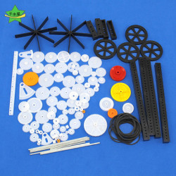
Metal shaft: suitable for TT motor tires and Mecanum wheels with special couplings
【Notes】
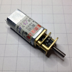
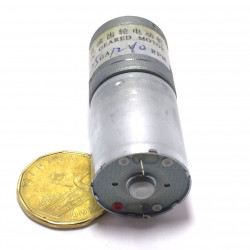
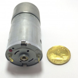
Warm reminder: The motor interface is PH2.06P interface, and the motor length is a little longer than the ordinary TT motor. That is because a magnetic encoder is added to the tail of the motor. Please check whether the motor size diagram is suitable for the installation of your car chassis. No further notice will be given!!
Wiring instructions: Wiring as shown in the product interface diagram above, M+ and M- are motor drive signals (used to connect the motor drive module); VCC and GND are motor encoder power supply interfaces (compatible with 3.3V and 5V voltages), and A and B pins are connected to the microcontroller I/O port (used for the microcontroller to read the encoder signal). Please note: Do not connect the encoder power supply and AB pins to the motor drive signal end by mistake, otherwise the magnetic encoder will be burned!
Installation size tips: Due to the long length of this motor, it is temporarily not suitable for installation on the acrylic and PCB four-wheel drive smart car chassis on the market. Two-wheel drive and aluminum alloy chassis can be used compatibly.