.png)
All pictures are for illustrative purposes only.
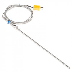
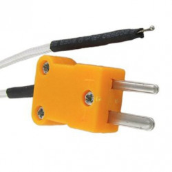
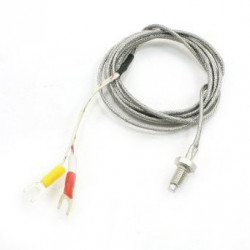
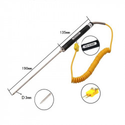
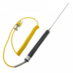
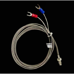
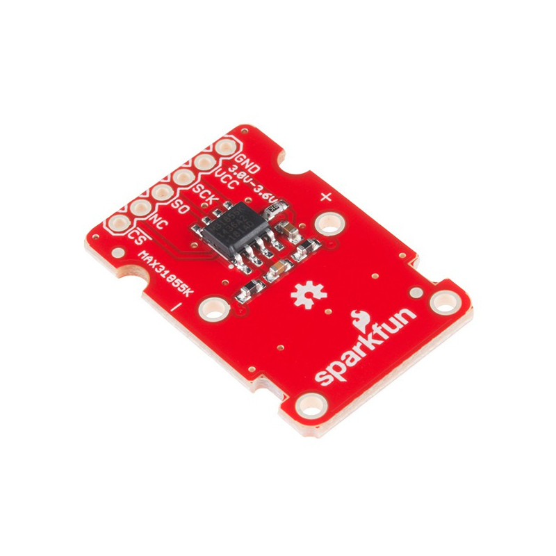
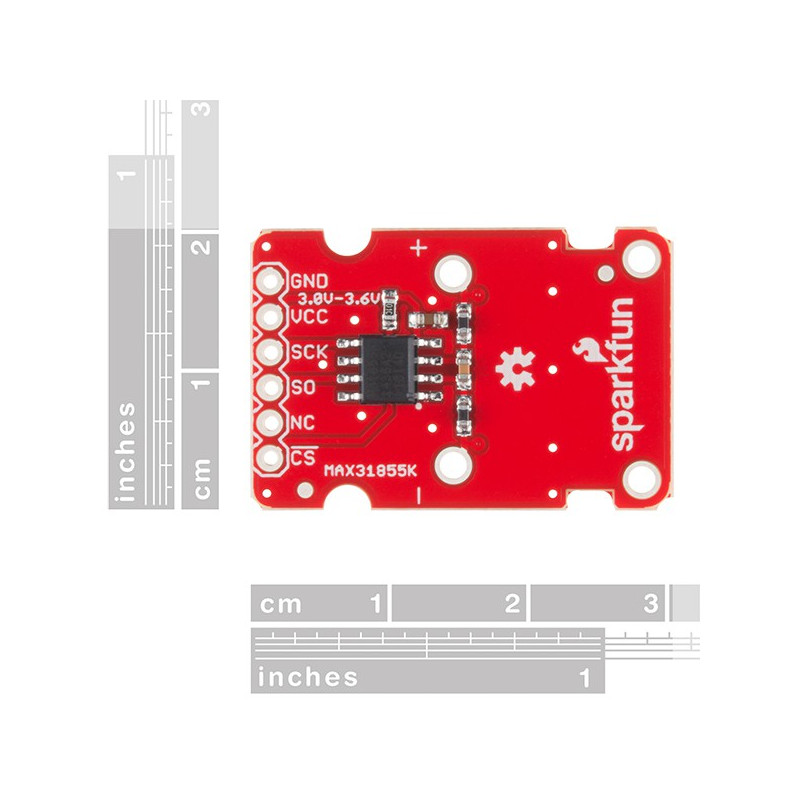
A thermocouple works by taking two wires made of dissimilar metals, connecting them at the two ends, and making a temperature gradient between one end and the other (a ‘hot’ end and a ‘cold’ one). Once this is achieved, a voltage potential is formed and current flows. The SparkFun Thermocouple Breakout takes a standard Type-K thermocouple in one end, digitizes the temperature measured and sends that data out the other end via a SPI interface, thereby interpreting the data and translating it for you to read!
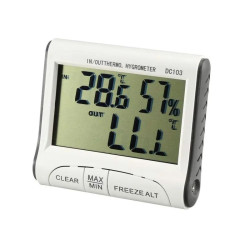
With the SparkFun Thermocouple Breakout, the thermocouple’s hot junction can be read from -200°C to +700°C with an accuracy of ±2°C while the cold junction, inside the MAX31855K, can only range from -20°C to +85°C while maintaining ±2°C accuracy. The MAX31855K constantly measures the temperature of the cold junction using an internal temperature-sensing diode. The MAX31855K requires a power source from +3.0V to +3.6V (+3.0V nominal) and only draws 1.5mA maximum.
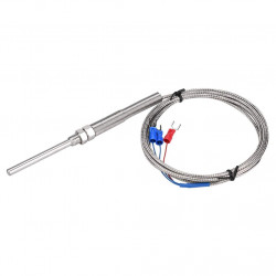
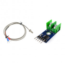
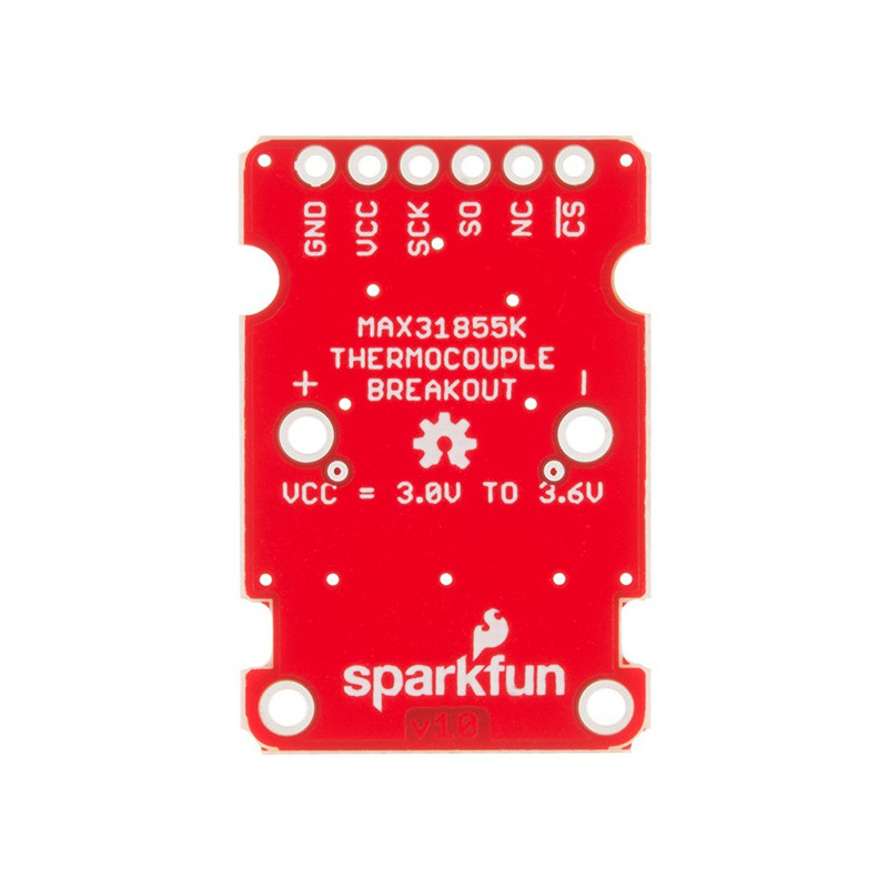
The Thermocouple Breakout is designed to accept a standard thermocouple connector, for convenience and compatibility with probes you may already own. These connectors aren’t necessary, and you could solder a thermocouple directly into the through-holes labeled ‘+’ and ‘-’. If you decide to solder the thermocouple directly to the breakout board, it is recommended that the thermocouple be mounted for strain relief to avoid breaking the thin wires. Notches for a zip-tie or wire wrapping have been provided in the PCB opposite the header for this purpose.