

location_on 4131 Fraser St. Vancouver BC Get Directions
phone 604-875-1993 Call us
access_time Hours
| Monday - Friday | 9AM - 5:30PM |
| Saturday - Sunday & Holidays | Closed | See Holiday Hours |


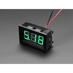
Put a current meter anywhere with this very handy display. This panel meter requires a DC voltage to run, and then has two thick gauge wires to measure current draw. A shunt is already on board so its very easy to hook up!
Since current sensors are a little more complex than volt meters, and its easy to confuse the wires, please read carefully to understand how to wire it together! The current meter has two sets of wires, one thin (red and black) and one thick (red or white, and black). The thin wire set is for powering the meter itself and must be 4.5-30VDC. There is reverse-polarity protection on these wires. The thick wire set is for the in-line current sensing. The black sensing wire is tied to the black power wire internally, so depending on how you want to use the meter, you may need a separate power circuit (see the next paragraph)
The easiest and safest way to use the meter is to have no electrical connection between the powering and sensing current. That is, connect something like a 9V battery to the thin power wires and you can put the current sensor in anywhere you want. As long as the circuits are totally separate this will work great.
Another option is to have one circuit power the meter while it is sensing the same circuit. To do this, you'll need to make sure that you are low-side sensing. This is because the ground power wire is connected to the black current sense wire. To make sure you don't accidentally short your power supply, you'll need to arrange your circuit so that the ammeter sits 'right below' the "ground" of whatever you are sensing. See the image above for a diagram showing how to measure motor current, for example. Make sure the DC power is between 4.5V and 30V in this case.
The display has a microcontroller that will read the current through the shunt resistance, compare it to a stable reference and display the current in Amps on a 3-digit 0.56" tall 7-segment display. It works from 4.5V up to 30V and is reverse-polarity protected so it will be good for nearly any electronic project! The meter itself draws about 20mA to power the microcontroller and display. This particular LED display is a nice contrast red, which we found very readable. To mount to your enclosure, simply cut a 45.5mm × 26.5mm rectangle and snap it in.
Since current sensors are a little more complex than volt meters, and its easy to confuse the wires, please read carefully to understand how to wire it together! The current meter has two sets of red/black wires, one thin and one thick. The thin wire set is for powering the meter itself and must be 4.5-30VDC. There is reverse-polarity protection on these wires. The thick wire set is for the in-line current sensing. The black sensing wire is tied to the black power wire internally, so depending on how you want to use the meter, you may need a separate power circuit (see the next paragraph)
The easiest and safest way to use the meter is to have no electrical connection between the powering and sensing current. That is, connect something like a 9V battery to the thin power wires and you can put the current sensor in anywhere you want. As long as the circuits are totally separate this will work great.
Another option is to have one circuit power the meter while it is sensing the same circuit. To do this, you'll need to make sure that you are low-side sensing. This is because the ground power wire is connected to the black current sense wire. To make sure you don't accidentally short your power supply, you'll need to arrange your circuit so that the ammeter sits 'right below' the "ground" of whatever you are sensing. See the image above for a diagram showing how to measure motor current, for example. Make sure the DC power is between 4.5V and 30V in this case.
The display has a microcontroller that will read the current through the shunt resistance, compare it to a stable reference and display the current in Amps on a 3-digit 0.56" tall 7-segment display. It works from 4.5V up to 30V and is reverse-polarity protected so it will be good for nearly any electronic project! The meter itself draws about 20mA to power the microcontroller and display. This particular LED display is a nice contrast red, which we found very readable. To mount to your enclosure, simply cut a 45.5mm × 26.5mm rectangle and snap it in.

