

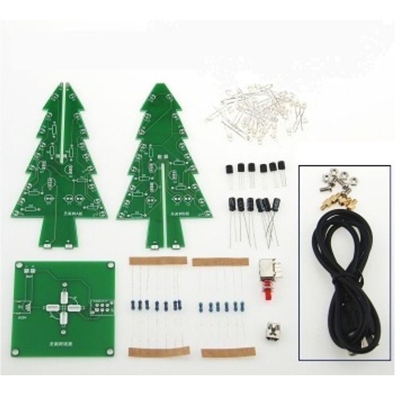
All pictures are for illustrative purposes only.
The circuit principle is as follows: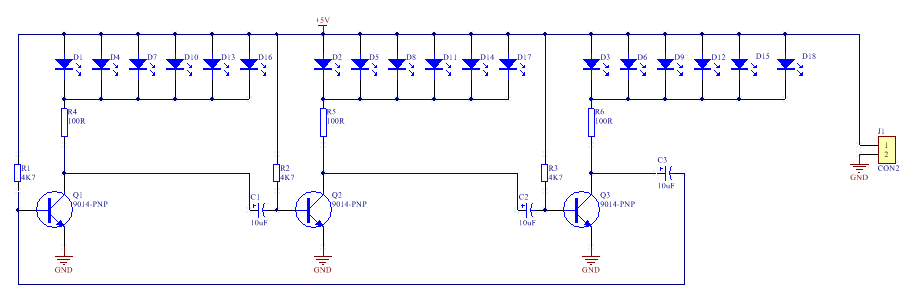
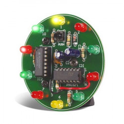
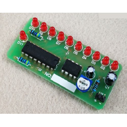
Working principle: It can be seen from the schematic diagram that when connected to a 3-5V power supply, the 18 LEDs are divided into 3 groups. Whenever the power is turned on, the 3 triodes will compete to conduct first. A triode is turned on first, here it is assumed that Q1 is turned on first, and the group of LED1 lights up. Since Q1 is turned on, its collector voltage drops and the left end of capacitor C2 drops, which is close to 0V. Since the voltage at both ends of the capacitor cannot change abruptly, Q2 The base of Q2 is also connected to approximately 0V, and Q2 is cut off, so the group of LED2 connected to its collector goes out; at this time, the high voltage of Q2 increases the collector voltage of Q3 through capacitor C3, and Q3 will also be turned on quickly. The LED3 group is on, so for a period of time, the collectors of Q1 and Q3 are both low, the two groups of LED1 and LED3 are on, and the LED2 group is off, but as the power passes through the resistor R2 to C2 Charging, the base voltage of Q2 rises gradually. When it exceeds 0.7V, Q2 changes from off state to on state, the collector voltage drops, and the group of LED2 lights up. At the same time, the voltage of the collector of Q2 drops Through C3, the base voltage of Q3 also decreases, Q3 turns from on to off, its collector voltage rises, and the group of LED3 goes out. Next, the circuit circulates according to the process described above, and the three groups of 18 LEDs will be It will be turned on in turn, and two groups of LEDs will be lit at the same time. These LEDs are arranged in a heart-shaped pattern, and they flash and glow in a continuous cycle to achieve the effect of a flowing display.
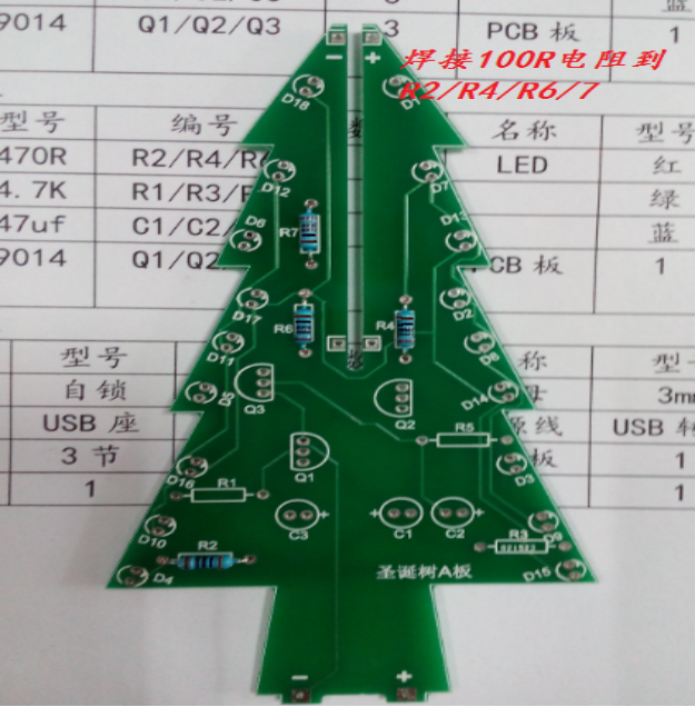
1. Welding of boards A and B of the Christmas tree (the welding method of the two boards is the same, compared with the two boards, board B has less R7 )
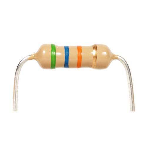
1. Weld the 100R resistor ( there is no direction, it is marked on the resistor when it is shipped, don’t weld it wrong )
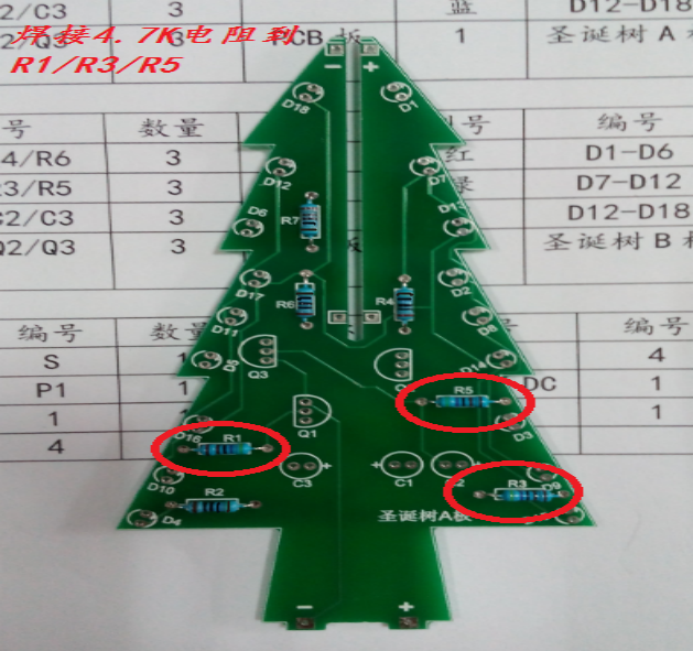
2. Weld the 4.7K resistor ( there is no direction, it is marked on the resistor when it is shipped, don’t weld it wrong )
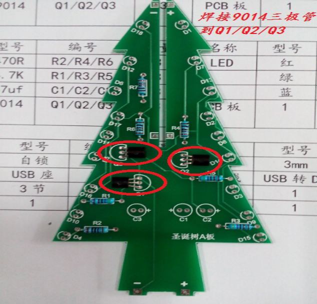
3. Welding 9014 ( direction, soldering against the direction of the circuit board silk screen )
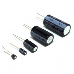
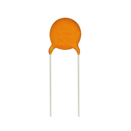
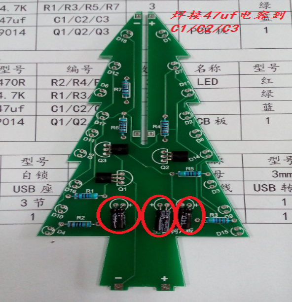
4. Weld 47uf electrolytic capacitor ( with direction, the long leg is positive )
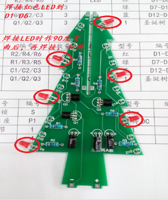
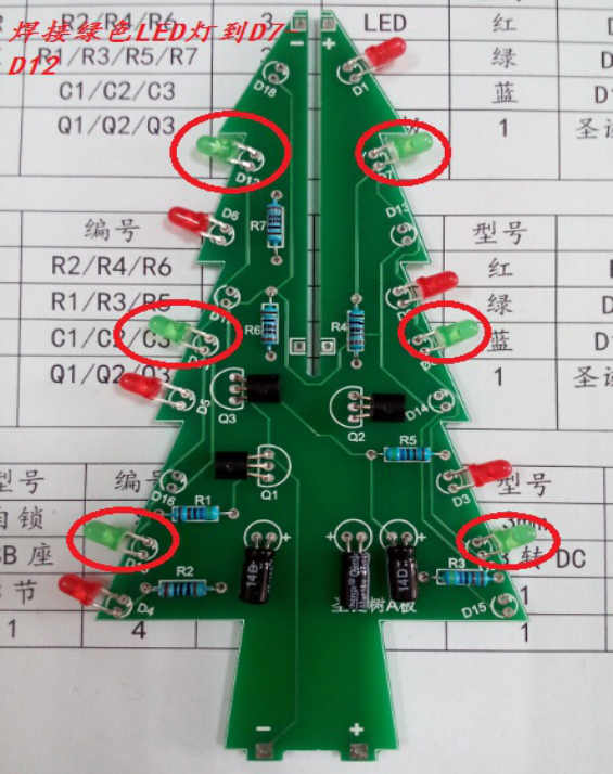
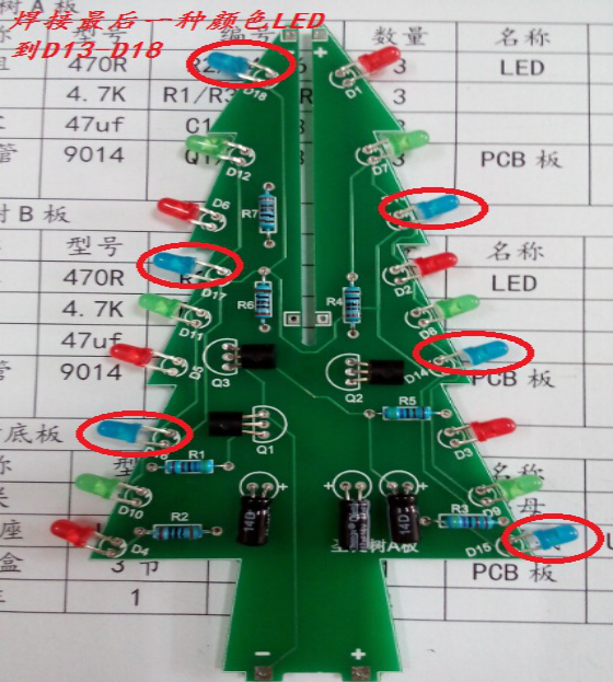
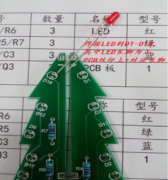
5. Welding the LED , The LED are all the same and can be welded anywhere ( there is a direction, the long leg is positive, and the soldering iron cannot weld both LED pins at the same time )
6. Solder the top led , and use red for the three-color lamp version ( note: you need to combine boards A and B before welding )
2. Welding the bottom plate of the Christmas tree
Solder the silk screen P1 of the bottom plate to the power plug, and S to the self-locking switch.

3. Schematic diagram of connection between boards A and B and the bottom board
After the plates A and B are clamped, the "+" sign corresponds to the "+" sign (viewed from the side of the self-locking switch):

The number " one " corresponds to the number " one " (viewed from the side of the power interface)