


All pictures are for illustrative purposes only.
|
|
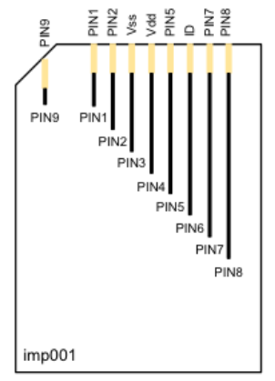
Pin Number |
Pin Name |
Description |
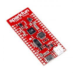
|
3 |
Vss |
Ground |
|
|
4 |
VDD |
Power input |
|
|
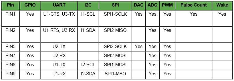
1,2,5,7,8&9 |
PIN1,2,5,7,8&9 |
I/O, please refer to Pin mux table |
|
|
6 |
ID |
Connects to the Atmel ATSHA ID chip |