


All pictures are for illustrative purposes only.
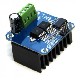
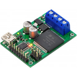
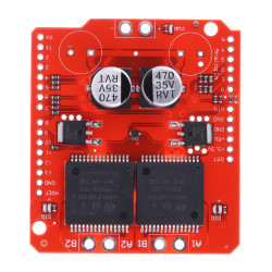
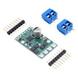
The Pololu G2 high-power motor driver is a discrete MOSFET H-bridge designed to drive large brushed DC motors. The H-bridge is made up of one N-channel MOSFET per leg; the rest of the board contains the circuitry to take user inputs and control the MOSFETs. The absolute maximum voltage for this motor driver is 40 V, and higher voltages can permanently destroy the motor driver. Under normal operating conditions, ripple voltage on the supply line can raise the maximum voltage to more than the average or intended voltage, so a safe maximum voltage is approximately 34 V.
Note: Battery voltages can be much higher than nominal voltages when they are charged, so the maximum nominal battery voltage we recommend is 28 V unless appropriate measures are taken to limit the peak voltage.
The versatility of this driver makes it suitable for a large range of currents and voltages: it can deliver up to 13 A of continuous current with a board size of only 1.3″ × 0.8″ and no required heat sink. The module offers a simple interface that requires as few as two I/O lines while still allowing for your choice of sign-magnitude or locked-antiphase operation. A current sense output gives an indicator of motor current, and the driver can limit the motor current to a configurable threshold. The power supply inputs feature reverse-voltage protection, while integrated detection of various fault conditions helps protect against other common causes of catastrophic failure; however, please note that the board does not include over-temperature protection.
The G2 High-Power Motor Driver 24v13 is a second-generation successor to our original High-Power Motor Driver 24v12 and can be used as a near drop-in replacement in typical applications. See “Differences from original high-power motor drivers” below for more details.
The motor and motor power connections are on one side of the board, and the control connections (1.8 V to 5 V logic) are on the other side. The motor supply should be capable of supplying high current. There are two options for making the high-power connections (VIN, OUTA, OUTB, GND): large holes spaced 5 mm apart, which are compatible with the included terminal blocks, and pairs of 0.1″-spaced holes that can be used with perfboards, breadboards, and 0.1″ connectors.
For good performance, it is very important to install a large capacitor across the motor supply and ground close to the motor driver. We generally recommend using a capacitor of at least a few hundred μF and rated well above the maximum supply voltage; the required capacitance will be greater if the power supply is poor or far (more than about a foot) from the driver, and it will also depend on other factors like motor characteristics and applied PWM frequency. A through-hole capacitor can be installed directly on the board in the holes labeled '+' and '−' (connected to VM and GND, respectively). The driver includes an on-board 100 uF capacitor, which might be sufficient for brief tests and limited low-power operation, but adding a bigger capacitor is strongly recommended for most applications.
Warning: Take proper safety precautions when using high-power electronics. Make sure you know what you are doing when using high voltages or currents! During normal operation, this product can gethot enough to burn you. Take care when handling this product or other components connected to it.
The logic connections are designed to interface with 1.8 V to 5 V systems (5.5 V max). By default, the driver is in a low-power sleep mode; the SLP pin should be driven or tied to a logic high voltage in order to enable the driver. In a typical configuration, only two other pins are required: PWM and DIR.