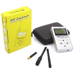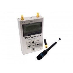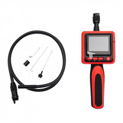


All pictures are for illustrative purposes only.
-
 close
close -
-
-
-
-
-
-
-
-
-
-
-
-
-
Featured Items
-
-
-
-
-
-
-
More mirco-controllers
-
More Developement Tools
-
-
More Prototyping
-
More Modules
-
-
Featured Items
-
More prototyping Tools
-
-
-
-
-
-
-
-
Featured Item
-
-
-
-
-
-
-
Featured Items
-
-
-
-
-
-
-
-
Featured Items
-
-
-
-
-
-
-
-
-
-
-
-
-
Featured Items
-
-
-
-
-
-
-
-
-
Featured Items
-
-
-
-
-
-
Popular Cleaners
-
-
-
Featured Items
-
-
-
-
-
-
-
Featured Items
-
-
-
-
-
Featured Items
-
-
-
-
Featured Products
-
-
-
-
-
more motor
-
-
more power supplies
-
-
Featured Items
-
-
-
more electrical devices
-
-
-
-
-
-
-
Featured Items
-
-
-
-
-
-
-
-
-
-
-
FEATURED POSTS
-
-
-
LCR-T4 TRANSISTOR/ESR/DIODE/TRIODE TESTER W/CASE
Description
Features
Operates with ATmega328 microcontrollers.
Displaying the results to a 128x64 graphic LCD-Display.
One key operation with automatic power shutdown.
Shutdown current is only about 20nA.
Automatic detection of NPN and PNP bipolar transistors, N- and P-Channel MOSFETs, JFETs, diodes, double diodes, Thyristors and Triacs.
Automatic detection of pin layout of the detected part.
Measuring current amplification factor and Base-Emitter threshold voltage of bipolar transistors.
Darlington transistors can be identified by the threshold voltage and high current amplification factor.
Detection of the protection diode of bipolar transistors and MOSFETs.
Measuring of the Gate threshold voltage and Gate capacity value of MOSFETs.
Up to two Resistors are measured and shown with symbols and values with up to four decimal digits in the right dimension. All symbols are surrounded by the probe numbers of the Tester (1-3). So Potentiometer can also be measured. If the Potentiometer is adjusted to one of its ends, the Tester cannot differ the middle pin and the end pin.
Resolution of resistor measurement is now up to 0.01Ω, values up to 50MΩ are detected.
One capacitor can be detected and measured. It is shown with symbol and value with up to four decimal digits in the right dimension. The value can be from 25pF to 100mF. The resolution can be up to 1pF .
For capacitors with a capacity value above 0.18µF the Equivalent Serial Resistance (ESR) is measured with a resolution of 0.01Ω and is shown with two significant decimal digits.
For capacitors with a capacity value above 5000pF the voltage loss after a load pulse can be determined. The voltage loss give a hint for the quality factor of the capacitor.
Up to two diodes are shown with symbol or symbol in correct order. Additionally the flux voltages are shown.
LED is detected as diode, the flux voltage is much higher than normal. Two-in-one LEDs are also detected as two diodes.
Zener-Diodes can be detected, if reverse break down Voltage is below 4.5V. These are shown as two diodes, you can identify this part only by the voltages. The outer probe numbers, which surround the diode symbols, are identical in this case. You can identify the real Anode of the diode only by the one with break down (threshold) Voltage nearby 700mV!
If more than 3 diode type parts are detected, the number of founded diodes is shown additionally to the fail message. This can only happen, if Diodes are attached to all three probes and at least one is a Z-Diode. In this case you should only connect two probes and start measurement again, one after the other.
Measurement of the capacity value of a single diode in reverse direction. Bipolar Transistors can also be analysed, if you connect the Base and only one of Collector or Emitter.
Only one measurement is needed to find out the connections of a bridge rectifier.
Capacitors with value below 25pF are usually not detectet, but can be measured together with a parallel diode or a parallel capacitor with at least 25pF. In this case you must subtract the capacity value of the parallel connected part.
For resistors below 2100Ω also the measurement of inductance will be done, if your ATmega has at least 16K flash memory. The range will be from about 0.01mH to more than 20H, but the accuracy is not good. The measurement result is only shown with a single component connected.
Testing time is about two seconds, only capacity or inductance measurement can cause longer period.
Software can be configured to enable series of measurements before power will be shut down.
Selectable facility to calibrate the internal port resistance of port output and the zero offset of capacity measurement with the selftest . A external capacitor with a value between 100nF and 20µF connected to pin 1 and pin 3 is necessary to compensate the offset voltage of the analog comparator. This can reduce measurement errors of capacitors of up to 40µF. With the same capacitor a correction voltage to the internal reference voltage is found to adjust the gain for ADC measuring with the internal reference. 10
Display the Collector cutoff current ICE0 with currentless base (10µA units) and Collector residual current ICES with base hold to emitter level . This values are only shown, if they are not zero (especially for Germanium transistors).
Thyristors and Triacs can only be detected, if the test current is above the holding current. Some Thyristors and Triacs need as higher gate trigger current, than this Tester can deliver. The available testing current is only about 6mA!