Store address and hours
location_on 4131 Fraser St. Vancouver BC Get Directions
phone 604-875-1993 Call us
access_time Hours
Monday - Friday | 9AM - 5:30PM |
Saturday - Sunday & Holidays | Closed | See Holiday Hours |
-
close
-
CATEGORIES
-
-
-
-
-
-
-
-
-
-
-
-
-
Featured Items
-
-
-
-
-
-
-
More mirco-controllers
-
More Developement Tools
-
-
More Prototyping
-
More Modules
-
-
Featured Items
-
More prototyping Tools
-
-
-
-
-
-
-
-
Featured Item
-
-
-
-
-
-
-
Featured Items
-
-
-
-
-
-
-
-
Featured Items
-
-
-
-
-
-
-
-
-
-
-
-
-
Featured Items
-
-
-
-
-
-
-
-
-
Featured Items
-
-
-
-
-
-
Popular Cleaners
-
-
-
Featured Items
-
-
-
-
-
-
-
Featured Items
-
-
-
-
-
Featured Items
-
-
-
-
Featured Products
-
-
-
-
-
more motor
-
-
more power supplies
-
-
Featured Items
-
-
-
more electrical devices
-
-
-
-
-
-
-
Featured Items
-
-
-
-
-
-
BRANDS
-
- PROJECTS
-
COMMUNITY
-
-
-
FEATURED POSTS
-
-
-
- SALE
GENUINO 101
Description
A learning and development board that delivers the performance and low-power consumption of the Intel® Curie™ Module with the simplicity of Arduino at an entry-level price.
It keeps the same robust form factor and peripheral list of the UNO with the addition of onboard Bluetooth LE capabilities and a 6-axis accelerometer/gyro to help you easily expand your creativity into the connected world.
The module contains two tiny cores, an x86 (Quark) and a 32-bit ARC architecture core, both clocked at 32MHz. The Intel toolchain compiles your Arduino sketches optimally across both cores to accomplish the most demanding tasks.
The Real-Time Operating Systems (RTOS) and framework developed by Intel is open sourced. See below under Firmware for the download link. The Arduino core communicates with the RTOS via static mailboxes to accomplish a predefined list of tasks (interface with PC using USB, program the sketch into flash, expose Bluetooth LE functionality to sketch, perform PWM). The RTOS for Intel Curie is still under development and new functions and features will be released in the near future.
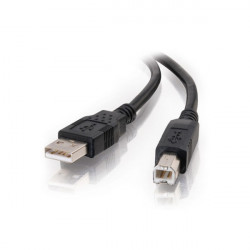
The 101 comes with 14 digital input/output pins (of which 4 can be used as PWM outputs), 6 analog inputs, a USB connector for serial communication and sketch upload, a power jack, an ICSP header with SPI signals and I2C dedicated pins.
The board operating voltage and I/O is 3.3V but all pins are protected against 5V overvoltage.
The Arduino 101 (USA only) and the Genuino 101 (outside USA) has been designed in collaboration with Intel®.
- On the Software on the Arduino Forum
- On Projects on the Arduino Forum
- On the Product itself through our Customer Support
Microcontroller | Intel Curie |
Operating Voltage | 3.3V (5V tolerant I/O) |
Input Voltage (recommended) | 7-12V |
Input Voltage (limit) | 7-20V |
Digital I/O Pins | 14 (of which 4 provide PWM output) |
PWM Digital I/O Pins | 4 |
Analog Input Pins | 6 |
DC Current per I/O Pin | 20 mA |
Flash Memory | 196 kB |
SRAM | 24 kB |
Clock Speed | 32MHz |
Features | Bluetooth LE, 6-axis accelerometer/gyro |
Length | 68.6 mm |
Width | 53.4 mm |
The board comes preprogrammed with an RTOS that handles USB connection and allows you to upload new code without the use of an external hardware programmer. It communicates using the DFU protocol (reference).
For people interested in compiling their own firmware, the source code and full details on how to use it are made available on the dedicated Intel's Download Page.
External (non-USB) power can come either from an AC-to-DC adapter (wall-wart) or battery. The adapter can be connected by plugging a 2.1mm center-positive plug into the board's power jack. Leads from a battery can be inserted in the GND and Vin pin headers of the POWER connector.
- VIN. The input voltage to the Arduino board when it's using an external power source (as opposed to 5 volts from the USB connection or other regulated power source). You can supply voltage through this pin, or if supplying voltage via the power jack, access it through this pin.
- 5V. This pin outputs a regulated 5V from the regulator on the board. The board can be supplied with power either from the DC power jack (7 - 12V), the USB connector (5V), or the VIN pin of the board (7-12V). Supplying voltage via the 5V or 3.3V pins bypasses the regulator, and can damage your board if it is not sufficiently regulated. We don't advise it.
- 3.3V. A 3.3 volt supply generated by the on-board regulator. Maximum current draw is 1500 mA. This regulator also provides power to the Curie microcontroller.
- GND. Ground pins.
- IOREF. This pin on the Arduino board provides the voltage reference with which the microcontroller operates. A properly configured shield can read the IOREF pin voltage and select the appropriate power source or enable voltage translators on the outputs for working with the 5V or 3.3V.
- Serial: 0 (RX) and 1 (TX). Used to receive (RX) and transmit (TX) TTL serial data. These pins are connected to the Serial1 class.
- External Interrupts on all pins. Can trigger an interrupt on a low value, high value, a rising or falling edge, or a change in value (change is only supported by pins 2, 5, 7, 8, 10, 11, 12, 13). See the attachInterrupt() function for details.
- SPI: SS, MOSI, MISO, SCK. Located on the SPI header support SPI communication using the SPI library.
- LED: 13. There is a built-in LED driven by digital pin 13. When the pin is HIGH value, the LED is on, when the pin is LOW, it's off.
- Analog Inputs. Six of the 20 general purpose I/O pins on the 101 provide analog input. These are labeled A0 through A5, and each provide 10 bits of resolution (i.e. 1024 different values). They measure from ground to 3.3 volts
- TWI: SDA pin and SCL pin. Support TWI communication using the Wire library